THE DIGITAL LOGIC INVERTER
30 likes | 167 Vues
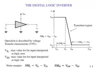
This text explores the transition region operation of digital logic inverters, focusing on the voltage transfer characteristic (VTC). It defines key parameters such as V_IL and V_IH, which specify the maximum voltage levels interpreted as logic zero and one, respectively. Furthermore, the document discusses the importance of noise margins in ideal cases, highlighting how an ideal inverter can maximize these margins and evenly distribute them across low and high voltage regions, ensuring optimal performance without a transition region.

THE DIGITAL LOGIC INVERTER
E N D
Presentation Transcript
THE DIGITAL LOGIC INVERTER Transition region Operation is described by voltage Transfer characteristic (VTC). VIL –max value for for input interpreted as logic zero VIH –max value for for input interpreted as logic one Noise margins 1-1
The Ideal VTC Ideal inverter maximizes noise margins And distributes them equally between The low and high regions. (No transition region.) 1-2