Download
1 / 18
180 likes | 361 Vues
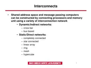
Investigating the Frequency Dependence Elements of CMOS RFIC Interconnects for Physical Modeling. B. H. Ong; C. B. Sia; K. S. Yeo; J. G. Ma; M. A. Do; E. P. Li School of Electrical and Electronic Engineering, Nanyang Technological University, Singapore 639798

E N D
Investigating the Frequency Dependence Elements of CMOS RFIC Interconnects for Physical Modeling B. H. Ong; C. B. Sia; K. S. Yeo; J. G. Ma; M. A. Do; E. P. Li School of Electrical and Electronic Engineering, Nanyang Technological University, Singapore 639798 Advanced RFIC(S) Pte Ltd, Singapore Institute of High Performance Computing, Singapore
DISCLAIMER! • Dr. Ong could not come due to compulsory service with the Singapore army • I (Lou Scheffer) have prepared this summary of the paper, using the paper itself and my correspondence about with him about this paper earlier • This is my interpretation of the work, not Dr. Ong’s. • I have been unable to contact him by email for correction, clarifications, etc. • He has not even seen, much less blessed, this talk. • So any mistakes here are my responsibility, and should not be blamed on Dr. Ong
Basic idea • Use an analog technique called “S parameters” to measure interconnect • Deduce a SPICE model from these measurements • Some energy is reflected, some absorbed, some transmitted. • Reflected is S11 and S22 • Transmitted is S12 and S21 RF in Component Port 2 Port 1
Why do this? • Some interconnect values are very hard to measure directly • Dominated entirely by test fixtures • C of wires • L of wires • Resistance if not at DC • S parameters can be cascaded, so effect of pads, bonding, etc. can be removed • Called “de-embedding”
Conclusions (Ong’s) • Wire models can be well fit (S parameters or Spice) up to very high frequencies
Conclusions (mine) • The models are well understood • The hardware folks can measure all values we want • So far they have measures of what the analog folks want • If we cooperate, they could easily measure more ‘digital’ parameters • Over lower metal, not substrate • All layers and widths • We need to cooperate with test structure folks