MIL-STD-1553
MIL-STD-1553. David Koppel. Excalibur Systems. Introduction. Review of MIL-STD-1553 Specification WHY? What need does it fill WHAT? What does the spec say HOW? How is it implemented. First Session. General Background on Avionics Buses Different Approaches ARINC-429 MIL-STD-1553

MIL-STD-1553
E N D
Presentation Transcript
MIL-STD-1553 David Koppel ExcaliburSystems
Introduction Review of MIL-STD-1553 Specification WHY? What need does it fill WHAT? What does the spec say HOW? How is it implemented
First Session • General Background on Avionics Buses • Different Approaches • ARINC-429 • MIL-STD-1553 • Firewire • AFDX
Second Session • Specification Details • Message Types • Mode Codes • Broadcast
Third Session • Implementation Issues • Prioritizing Messages • Maximizing Throughput
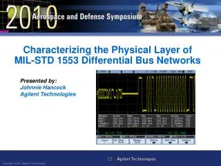
Fourth Session • Hardware Issues • Connections and Terminations • Using an Oscilloscope
Fifth Session • Software Applications
TERMS • Avionics Bus • Remote Terminal • Bus Controller • Bus Monitor • Source • Sink • Data Coupler • Dual Redundant • Minor Frame • Major Frame • Message
Examples of Clients Altimeter …… Display …… Black Box …… Flight Computer …… Active Device Passive Device Passive Device Active and Passive
First GenerationAnalog Devices One Device Altimeter Speedometer Compass One Display Gauge Gauge
Second GenerationARINC-429 Multiple Sink Display Auto Pilot Flight Recorder Display Auto Pilot Flight Recorder Maintenance Log One Device Altimeter Engine
Wiring Diagram Altimeter Display Auto Pilot Engine Flight Recorder Maintenance Log
Military Applications Multiple Device Missile # 1 Missile # 2 Missile # 3 Missile # 4 Multiple Sink Display Trigger Weapons Test Flight Recorder
Military ApplicationARINC-429 Wiring Multiple Device Missile # 1 Missile # 2 Missile # 3 Missile # 4 Multiple Sink Display Trigger Weapons Test Flight Recorder
Military ApplicationsMIL-STD-1553 Wiring Mission Computer (Bus Controller) Missile # 1 Missile # 2 Missile # 3 Missile # 4 Display Trigger Weapons Test Flight Recorder
1553 Advantages Low Weight Easy Bus Installation Easy to Add RT’s
Bus Controller Determines Order of Transmission Is Source or Sink for almost all Data Can check for bus errors
1553 Problem Solution Cable Cut = Crash Inefficiency Serial Transmission Xmt to / from BC BC Overhead BC Lost = Crash Dual Redundant Bus • 1 Mhz speed vs. 100 Khz for 429 • Minor Frames • Backup BC
Firewire / AS5643 Used in Video equipment and the F35 Wiring uses a binary tree configuration, each node passes the message through to its other nodes. Requires specialized Link and Phy hardware
ARINC-664 Part 7 / AFDX Based on Ethernet Adds dual redundancy No multiple routes – packets arrive in the order they are sent ~1500 bytes per packet Detection of lost or repeated data Relatively high overhead for short messages
Summary Direct lines are simple and cheap Multiple Transmit/Multiple Sink need a Bus Buses simplify H/W & Complicate S/W
Session 2 Goals of MIL-STD-1553 Mindset of MIL-STD Design Message Types MIL-STD-1760
Goals of MIL-STD-1553 • Communication between <= 32 Boxes • Low Data Requirement <= 32 Words • High Reliability • Ability to detect communication errors • Ability to retry on error
Mindset of MIL-STD Design • Military Approach • 1 Commander in Control • All others speak when spoken to • Commander speaks to one at a time or to all together (Broadcast)
1553 Message All Communication is by Message All Messages are Initiated by the BC All Messages begin with a Command Word
Message Types Bus Controller to RT Bus Controller to All RT’s (Broadcast) RT to Bus Controller Housekeeping messages (Mode Codes) RT to RT Commands
Message Format Messages Begin With A Command Word Data may flow to/from BC from/to RT RT’s return a Status Word
Command Word 5 Bits 1 Bit 5 Bits 5 Bits 15 11 10 9 5 4 0 RT Address T/R Bit Subaddress Word Count
Command Fields • RT Address • Address range is 0 - 31 • Some Systems use Address 31 as Broadcast • T/R Bit • If T/R = 1, RT Transmits Data • If T/R = 0, RT Receives Data
Command Fields • RT Subaddress • Additional Routing for Complex RT’s • May Correspond to Subsystems • Subaddress 0 is for Mode Codes • Subaddress 31 is MIL-STD-1553B Mode Code
Command Fields • Word Count • Range is 1 to 32 (field value 0 = 32 words) • For Mode Codes this is Mode Code Type • There are 16 Mode Codes with No Data • There are 16 Mode Codes with 1 word of Data
Status Word Bit #Description 15-11 RT Address 10 Message Error 8 Service Request 4 Broadcast Received 3 Busy
Status Bit Fields • RT Address • Lets BC Know Correct RT is Responding • Usually The Only Field Set • Message Error • Indicates a Communications Error
Status Bit Fields • Service Request (SRQ) • Indicates another Subaddress has info ready • Used with Get Vector Mode Command • Broadcast Received • Set in response to the message following a broadcast command • Busy • When RT can’t respond - discouraged by spec
Message Sequence . … Receive Command Data Word Data Word Data Word Status Word Next Command * . … Transmit Command Status Word Data Word Data Word Data Word Next Command * *
RT to RT Command Receive Command Transmit Command * Tx Status Word Data Word … Data Word * Rx Status Word . Next Command
Mode Commands . Mode Command Status Word Next Command * . Mode Command * Status Word Data Word Next Command . Mode Command Data Word Status Word Next Command *
MIL-STD-1760 Features • Checksum • SRQ Processing • Header Word Checking
Checksum • On selected messages in Bus Controller Mode • On selected RT/Subaddresses in RT Mode • For all messages in Monitor Mode
SRQ Processing • Send Vector Mode Command • If hi vector bit ==0 vector is a status wordelse send transmit command based on vector word
Header Word Checking • User selects which subaddress to check • User Selects header value for each subaddress • Default is based on 1760 standard
Session 3 • Implementation Issues • Timing • Major / Minor Frames • Implementation Examples
Timing Issues Intermessage Gap Time Response Time Major Frame Minor Frame
Intermessage Gap Time • Time Between Messages • At Least 4 usec Mid Sync to Mid Parity • No Maximum in Specification
Response Time • Time Until RT Sends A Status Word • MIL-STD-1553A Maximum = 7 usec • MIL-STD-1553B Maximum = 12 usec
Major Frame A Major Frame is the set of all messages in a single cycle Typical Cycle is 20 to 80 milliseconds Some messages may appear more than once in a single Major Frame
Minor Frames 10 Mill 10 Mill 10 Mill 10 Mill ABC AB A AB Some Messages Are High Priority We can alter frequency of specific messages
Example: Missile Test Does Pilot Wish To Perform a Test Instruct Missile to Execute Self Test Get Results Of Self Test Display Results On HUD
RT’s in Test Self Test Button on Console RT2 Missile RT3 Heads Up Display (HUD) RT4