Download
1 / 139
1.39k likes | 1.6k Vues
Unit 3 The Relational Model And From ER Diagram To Relational Database. Sets, Relations, and Tables. In this unit, we learn the semantics of specifying a relational database, later we will learn the syntax of SQL for doing this

E N D
Unit 3The Relational Model And From ER Diagram To Relational Database
Sets, Relations, and Tables • In this unit, we learn the semantics of specifying a relational database, later we will learn the syntax of SQL for doing this • The basic “datatype”, or “variable” of a relational database is a relation • In this unit, such a variable will be a set • Later, we will extend this, and such a variable will be a multiset • In SQL, such a variable is called a table • We may use the term table for a relation in this unit too • Good review of basic concepts and terminology is available at http://en.wikipedia.org/wiki/Relational_databases
Sets • We will not use axiomatic set theory • A set is a “bag” of elements, some/all of which could be sets themselves and a binary relationship “is element of” denoted by , such as 2 {2, 5, 3, 7}, {2,8} {2, {2, 8}, 5, 3, 7}, • You cannot specify • How many times an element appears in a set (if you could, this would be a multiset) • In which position an element appears (if you could, this would be a sequence) • Therefore, as sets: {2, 5, 3, 7} = {2, 7, 5, 3, 5, 3, 3} • Note: in many places you will read: “an element can appear in a set only once” This is not quite right. And it is important not to assume this, as we will see in a later unit
Sets • Two sets A and B are equal iff (if and only if) they have the same elements • In other words, for every x: x is an element of Aiff (if and only if) x is an element of B • In still different way: A and B are equal iff for every possible x, the questions “is x in A” and “is x in B” give the same answer • Note there is no discussion or even a way of saying how many times x appears in a set, really either none or at least once • “More mathematically,” A = B means x { x A x B } • Therefore, as sets: {2, 5, 3, 7} = {2, 7, 5, 3, 5, 3, 3} • This reiterates what we have said previously
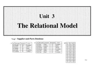
Relation • Consider a table, with a fixed number of columns where elements of each column are drawn from some specific domain • The columns are labeled and the labels are distinct • We will consider such a table to be a set of rows(another word for “row”: tuple) • An example of a table S of two columns A and B • A relation is such a table • We will also write S(A,B) for table S with columns A and B
Relational Schema • What we saw was an instance (current value for a relation with the defined columns and domains) • To specify this relation in general (not the specific instance) we need to talk about a relational schema • A relational schema defines a set of relations • In databases everything is finite, so a relational schema defines a finite set of finite relations
Relational Schema • Here is an informal, but complete, description what is a relational schema of one relation • We want to define a structure for some table • We give it a name (we had S) • We chose the number of columns (we had 2) and give them distinct names (we had A and B) • We decide on the domains of elements in the columns (we had letters for A and integers for B) • We decide on constraints, if any, on the permitted values (for example, we can assume as it was true for our example that any two rows that are equal on A must be equal on B)
Relational Schema • Let’s verify • A: all lower case letters in English • B: all positive integers less than 100 • S(A,B) satisfies the condition that any two tuples that are equal on A must also be equal on B • Our example was an instance of this relational schema
Relations • Since relations are sets of tuples, the following two relations are equal (are really one relation written in two different ways) (This is a different example, not an instance of the previous relational schema)
Relations • Since the positionsin the tuple (1st, 2nd, etc.) are labeled with the column headings, the following two relations are equal(are really one relation written in two different ways)
Relations • To specify relations, it is enough to do what we have done above • As long as we understand what are the domains for the columns, the following are formally fully specified relations (recall Unit 1) • Relational (schema) P(Name, SSN, DOB, Grade) with some (not specified, but we should have done it) domains for attributes • Relational (schema) Q(Grade, Salary) with some (not specified, but we should have done it) domains for attributes
Relations • But we will do more. We will specify, as suitable for the schema: • Primary keys • Keys (beyond primary) • Foreign keys and what they reference (we will see soon what this means) • Additional constraints • Some of the constraints involve more than one relation • The above are most important structurally • Later, when we talk about SQL DDL, we will specify additional properties
Keys (and Superkeys) • Consider relation (schema) Person(FN, LN, Grade, YOB) • Instance: • We are told that any two tuples that are equal on both FN and LN are (completely) equal • We have some tuples appearing multiple times: this is just for clarifying that this permitted in the definition, we do not discuss here why we would have the same tuple more than one time (we will talk about this later) • This is a property of every possible instance of Person in our application—we are told that • Then (FN, LN) is a superkey of Person, and in fact a key, because neither FN nor LN by themselves are sufficient (we are told that too)
Keys (and Superkeys) • Consider relation (schema) Q(Grade, Salary) • Example: • We are told that for any instance of Pay, any two tuples that are equal on Grade are (completely) equal • Of course, if each Grade appears in only one tuple, this is automatically true • Then, similarly to before, Grade is a key • What about Salary, is this a key also? • No, because we are not told (that is, we are not guaranteed) that any two tuples that are equal on Salary are equal on Grade in every instance of Pay
Keys (and Superkeys) • A set of columns in a relation is a superkey if and only any two tuples that are equal on the elements of these columns are (completely equal) • A relation always has at least one superkey • The set of all the attributes is a superkey • Because any two tuples that are equal on all attributes are completely equal • A minimal superkey, is a key • A relation always has at least one key (start with any superkey and remove unnecessary columns) • There may be more than one key • Exactly one key is chosen as primary key • Other keys are just keys • Sometimes they are called candidate keys (as they are candidates for the primary key, though not chosen)
Keys (and Superkeys) • To summarize • Superkey: a set of columns whose values determine the values of all the columns in a row for every instance of the relation • All the columns are a superkey (trivially) • Key: a set of columns whose values determine the values of all the columns in a row for every instance of the relation, but any proper subset of the columns does not do that • Primary Key: a chosen key
Keys (and Superkeys) • We will underline the attributes of the chosen primary key • Returning to Unit 2 and example of City: City(Longitude,Latitude,Country,State,Name,Size) • We can have • City(Longitude,Latitude,Country,State,Name,Size) • This implies that Longitude,Latitude form a primary key • We also have a candidate key: Country,State,Name • We can have • City(Longitude,Latitude,Country,State,Name,Size) • This implies that Country,State,Name form a primary key • We also have a candidate key: Longitude,Latitude
Relational Databases • A relational database is “basically” a set of relations • It is an instance of a relational schema • This is what is formally correct, but it is misleading in practice • As we will see later, a relational database is • A set of relations • A set of binary, many-to-one mappings between them (partial functions) • We will know later what this means exactly, but I did not want to leave you with not quite a useful definition
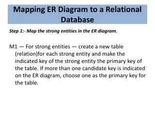
From ER Diagrams To Relational Database • We are now ready to convert ER diagrams into relational databases • Generally, but not always • An entity set is converted into a table • A relationship is converted into a table • We will first go through a simple example • Then, we will go through our large example, studied previously • Then, we look at some additional points of interest • Finally, we summarize the process, so we are sure we understand it
More About The Example • The given ER diagram is clear, other than • Discovered, which is the continent in which a particular species was first discovered • Each child is a “dependent” of only one employee in our database • If both parents are employees, the child is “assigned” to one of them • We are given additional information about the application • Values of attributes in a primary key must not be missing (this is a general rule, not only for this example) • Other than attributes in a primary key, other attributes, unless stated otherwise, may be missing • The value of Name is known (not missing) for every Employee • To build up our intuition, let’s look at some specific instance of our application
Small Example • 5 Employees: • 1 is Alice has Erica and Frank, born in US, likes Horse and Cat • 2 is Bob has Bob and Frank, born in US, likes Cat • 4 is Carol • 5 is David, born in IN • 6 is Bob, born in CN, likes Yak • 4 Countries • US • IN has 1150 • CN has 1330 • RU • 4 Animals • Horse in Asia • Wolf in Asia • Cat in Africa • Yak in Asia • Zebra in Africa
Country • There are four countries, listing for them: Cname, Population (the latter only when known): • US • IN, 1150 • CN, 1330 • RU • We create a table for Country “in the most obvious way,” by creating a column for each attribute (underlining the attributes of the primary key) and this works: • Note that some “slots” are NULL, indicated by emptiness
Animal • There are five animals, listing for them: Species, Discovered (note, that even though not required, Discovered happens to be known for every Species): • Horse, Asia • Wolf, Asia • Cat, Africa • Yak, Asia • Zebra, Africa • We create a table for Animal as before, and this works:
Employee • There are five employees, listing for them: ID#, Name, (name of) Child (note there may be any number of Child values for an Employee, zero or more): • 1, Alice, Erica, Frank • 2, Bob, Bob, Frank • 4, Carol • 5, David • 6, Bob, Frank • We create a table for Employee in the most obvious way, and this does not work:
Employee • Child is a multivalued attribute so, the number of columns labeled “Child” is, in principle, unbounded • A table must havea fixed number of columns • It must be an instance in/of a relational schema • If we are ready to store up to 25 children for an employee and create a table with 25 columns for children, perhaps tomorrow we get an employee with 26 children, who will not “fit” • We replace our attempted single table for Employee by two tables • One for all the attributes of Employee other than the multivalued one (Child) • One for pairs of the form (primary key of Employee, Child) • Note that both tables have a fixed number of columns, no matter how many children an employee has
Employee And Child • Replace (incorrect) By (correct)
Employee And Child With Better Column Names • Replace (incorrect) By (correct)
Employee And Child • The primary key of the table Employee is ID# • The primary key of the table Child is the pair: ID#,Child • One attribute is not sufficient to get a primary key for Child • It is clear from the example how to handle any number of multivalued attributes an entity has • Create a “main” table with all the attributes other than multivalued ones Its primary key is the original primary key of the entity set • Create a table for each multivalued attribute consisting a primary key for the main table and that multivalued attribute Its primary key is the primary key of the entity combined with the multivalued attribute
Foreign Key • Let us return to our example • Note that any value of ID# that appears in Child must also appear in Employee • Because a child must be a dependent of an existing employee • This is an instance of a foreign key • ID# in Child is a foreign key referencing Employee • This means that ID# appearing in Child must appear in some row “under” columns (here only one) of primary key in Employee • Note that ID# is not a key of Child (but is part of a key), so a foreign key in a table does not have to be a key of that table
Foreign Key ≡ A Binary Many-To-One Relationship Between Tables (Partial Function) • Note: • Every row of Child has a single value of a primary key of Employee, so every row of Child “maps” to a single row of Employee • Every row of Employee has zero or more rows of Child mapped into it In other words, no constraint
Foreign Key ≡ A Binary Many-To-One Relationship Between Tables • Another option • Note names do not have to be the same for the mapping to take place • But you need to specify which column is foreign key referring to what • Here: Parent in Child is foreign key referencing Employee
Born • Born needs to specify which employees were born in which countries (for whom this information is known) • We can list what is the current state • Employee identified by 1 was born in country identified by US • Employee identified by 2 was born in country identified by IN • Employee identified by 5 was born in country identified by IN • Employee identified by 6 was born in country identified by CN
Born • Born needs to specify who was born where • We have tables for • Employee • Country • We know that each employee was born in at most one country (actually was born in exactly one country but we may not know what it is) • We have a binary many-to-one relationship between Employee and Country
Implementation For Born • Augment Employee so instead of we have
Implementation For Born • Augment Employee so instead of we have two tables and a binary many-to-one mapping
Foreign Key Constraint Implementing Born • We have again a foreign key constraint • Any value of Cname in Employee must also appear in Country as a primary key in some row • Cname in Employee is a foreign key referencing Country • Note that Cname in Employee is not even a part of its primary key
Foreign Key Constraint Implementing Born • Perhaps better (and frequently done in practice) use a different name for foreign keys • Any value of CBirth in Employee must also appear in Country as a primary key in some row • CBirth in Employee is a foreign key referencing Country • We will not talk about such, possibly convenient, renaming
Likes • Likes needs to specify which employees like which animals • We can list what is the current state: • Employee identified by 1 likes animal identified by Horse • Employee identified by 1 likes animal identified by Cat • Employee identified by 2 likes animal identified by Cat • Employee identified by 6 likes animal identified by Yak
Likes • We can describe Likes by drawing lines between the two tables • We need to “store” this set of red lines • Likes is a many-to-many relationship • It is not a many-to-one relationship and therefore it is not a partial function
Likes (impossible implementation) • Cannot store with Employee (there is no limit on the number of animals an employee likes)
Likes (impossible implementation) • Cannot store with Animal (there is no limit on the number of employees who like an animal)
Likes • Each red line is an edge defined by its vertices • We create a table storing the red lines; that is, its vertices • We can do this using the primary keys of the entities We do not need other attributes such as Name or Discovered • The table for Likes contains tuples: • 1 likes Horse • 1 likes Cat • 2 likes Cat • 6 likes Yak
Likes • Note that there are foreign key constraints • ID# appearing in Likes is a foreign key referencing Employee • Species appearing in Likes is a foreign key referencing Animal • And two many-to-one mappings are induced • Note: a binary many-to-many relationship was replaced by a new table and two many-to one relationships
Using Visio • We will use Visio for designing/specifying relational databases • You can look at a tutorial, to get familiar with the mechanics of Visio • This is greatly oversimplified, but a good start • http://www.youtube.com/watch?v=1BYt3wmkgXE but foreign keys are not explained • http://www.youtube.com/watch?v=55TpWp4TmMw&NR=1 • http://www.youtube.com/watch?v=r0x8ZMyPoj4&NR=1 but this third part • Is misleading in the context of relational databases, due to the handling of many-to-many relationships and • They use of the second page, all the pages in a single Visio drawing refer to a single ER diagram, so each ER diagram needs its own Visio drawing/file
Specifying A Relational Implementation • We will use Visio to specify our relational implementation • And in fact, we could even use software to generate database specifications from the diagram to SQL DDL • We will just focus for now on the first task
Specifying A Relational ImplementationUsing Visio 2010 • A drawing in Visio is not an Entity Relationship Diagram tool despite such terminology in Visio • This is good, as it produces a relational schema, which is what we actually need, but this is a lower-level construct • It focuses on tables and the implicit many-to-one binary relationships induced by foreign key constraints • Table • A rectangle with three vertical subrectangles: name, list of attributes in the primary key, list of attributes not in the primary key • Required attributes are in bold • Attributes in the primary key and foreign keys are labeled as such • Relationship • A many-to-one binary (or perhaps one-to-one, which is a special case) relationship induced by a foreign key constraint is explicitly drawn by means of a segment with an arrow head We will have alternative notations later
Cardinality Constraints • The statement that a relationship is many-to-one as opposed to be a “standard” many-to-many relationship is really a cardinality constraint • We will look at a relationships Likes between Person and Country and four cases of cardinality constraints on how many Countries a Person may like • No constraint • At least one • At most one • Exactly one • For the first two, Likes is many-to-many • For the last two, Likes is many-to-one • Intuitively, Likes is many to one if for every Person, when you see which Countries this Person Likes, you get 0 or 1 • If you always get 1, this is a total function, otherwise this is a partial function