ILC Research and Development Plan for the Technical Design Phase
270 likes | 425 Vues
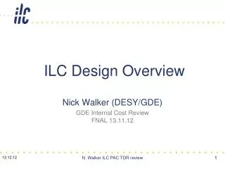
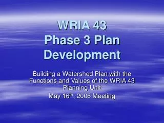
ILC Research and Development Plan for the Technical Design Phase. 設楽 GDE 活動報告会 2008.5.26. 2011. 2012. 2010. 2009. 2005. 2006. 2007. 2008. GDE process. RDR. TDP 2. Tech, Design Phase 1. construction. commissioning. physics. site selection. CLIC R&D. EUROTeV.

ILC Research and Development Plan for the Technical Design Phase
E N D
Presentation Transcript
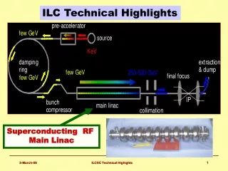
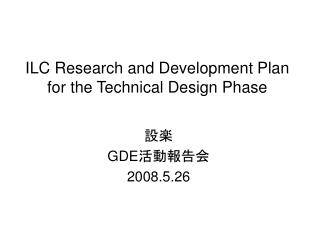
ILC Research and Development Planfor the Technical Design Phase 設楽 GDE活動報告会 2008.5.26
2011 2012 2010 2009 2005 2006 2007 2008 GDE process RDR TDP 2 Tech, Design Phase 1 construction commissioning physics site selection CLIC R&D EUROTeV ILC New Projected Time Line LHC physics
“Black December” “Both the UK and US actions are programmatic budget cuts and not rejections of the scientific goals and priorities that have motivated our work toward a linear collider.” -BB
ILC R&D Plan for TDPとは? • ILC GDEのTDPにおけるR&Dについてまとめたもの 2007年10月に出された”the ILC Project Management Plan for the Technical Design (TD) Phase”を補うもの。この”ED Phase Project Management Plan” については、横谷さんによる2007.9.25のGDE活動報告会「GDE新組織について」を参照のこと。 • 経過 2007年11月より準備開始 2007年12月、UK/USA Black Decemberの影響で見直し Revision 2 – 2008.02 FALC-RGに提示 Revision 3 – 2008.05 FALC-RGに再提示
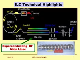
3 R&Dのゴール • R&Dのゴールは、デザインチョイスを認証し、コスト削減やリスクを軽減するデザインのアップデートを図ること。 • TDP Project Managementには直接的な財源や人的資源がないので、TDP Planには通常の意味での期限付きの到達目標が載せられていない。かわりに、リスクとコスト削減に大きなインパクトを持つと思われる次の3つの活動プランを載せている。 1. 超伝導加速空洞加速勾配の研究と空洞システム試験; 2. 概念設計の建築・施設についての”Value Engineering”; 3. ビーム加速試験施設; (4. Cost Management.)
Technical Responsibilities : • Green indicates a commitment: • institute will deliver • MoUs facilitate connection: • Project Management (authority and responsibility) and institutions (funding and resources). • The ‘C’ coordinating role in a WP • Each WP has one coordinator.
5 Primary TD Phase goals5.1.1 Primary SCRF goals • Cavity: High-gradient R & D with single-cell and 9-cell cavities, for the material, forming and surface-preparation process, and vertical test to achieve the field gradient 35 MV/m at Q0 = 10**10 with the yield > 90% (> 80% at 1st test, and >90 % after re-processing remaining 20%); • Cavity-integration: Plug-compatible cavity-package design and integration including tuner, input-coupler, He-vessel and magnetic shield, and the cavity string test with average gradient of 31.5 MV/m in one cryomodule (S1);
• Cryomodule: Plug-compatible cryomodule design and integration with the cost effective fabrication will be studied. The design of such components as the 5-K shield will be simplified; • Cryogenics: system engineering to establish cost-effective design in both construction and operation. The adequate coordination needed to satisfy pressure vessel codes in each region will be investigated. • HLRF: development of a cost-effective modulator and power distribution system capable of managing cavity field gradients which deviate from the nominal value; • MLI: General alignment of SCRF and beam handling components such as quadrupole magnets and diagnostics to be investigated and the design optimization is required. • SCRF-system integration: System integration and test of three cryomodules containing 9 (or 8) ×9-cell full-dressed cavities and an RF-system unit will be carried out with a goal to achieve an average accelerating gradient of 31.5 MV/m at Q0 = 10**10 including beam acceleration and handling with a quadrupole magnet and beam monitoring system in the central module (S2);
5.2 CF&S and Global Systems5.2.1 Primary CFS/Global TD Phase goals • develop and analyze functional requirements as specified by the Accelerator Systems; • validate the design based on functional requirements; • execute the ‘Value Engineering’ review process, with special focus on the most costly aspects of the design: o underground construction; o process water cooling; o air handling; o surface construction. • evaluate results of the review process and recommend decisions; • complete TD Phase effort with an updated and improved baseline.
5.2.2 CFS/Global Milestones CFS Milestones mark progress toward bringing the designs to maturity and to do cost – benefit analysis in order produce a cost / risk optimized design and ILC project plan. These milestones include: • defining and delivering technical requirements and criteria to be used in CFS design efforts; • completing value engineering analysis leading to an Accelerator System and CFS cost / risk optimum design; • evaluating and deciding which proposed cost-saving proposals will be adopted and included in the TDR.
5.3 Accelerator Systems5.3.1 Primary Accelerator Systems TD Phase goals • define and clearly document performance-driven specifications for the accelerator components and – more critically – CFS; • iterate with the relevant engineering groups to understand the cost/performance trade-offs, with CFS as a focus; • demonstrate that the accelerator design fulfils the required performance goals (in a cost-effective way), by demonstration via critical R & D or by simulation; • maintain design-related risk register, and develop alternative fall-back (risk mitigating) solutions.
5.3.2 Accelerator Systems Milestones TD Phase 1 (2010) • R&D into mitigation of high-risk accelerator physics and design aspects of the collider. Specifically demonstration of suppression techniques for electron cloud effects in small emittance beams for the Damping Ring, and demonstration of the Beam Delivery optics and the required demagnification of the beam at the interaction point. Both of these critical programs rely strongly on Test Beam Facilities currently in planning (CESR-TA and ATF-2 respectively). • Consolidation and review of the Reference Design Report machine design and associated VALUE estimate, leading to selected cost-reduction (performance versus cost) studies, leading to a re-baseline of the machine layout in 2010 in preparation for subsequent technical design and costing activities in Phase 2. • Continued critical beam dynamics studies to evaluate design performance. In particular understanding cost/performance trade-offs arising from selected engineering studies as needed.
5.3.2 Accelerator Systems Milestones TD Phase 2 (2012) • Complete (cost optimized) engineering layout of the updated baseline for the all accelerator sub-systems, with consolidated and detailed component lists with specifications suitable for engineering, and accurate enough to support the VALUE estimate. • Complete CFS criteria tables, which have been reviewed and interacted (value engineered) at least once for each accelerator system. • Completion of additional selected critical R&D items (specifically in the BDS and electron and positron sources.)