Joint Definition - Friction
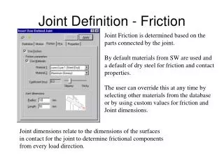
Joint Definition - Friction. Joint Friction is determined based on the parts connected by the joint. By default materials from SW are used and a default of dry steel for friction and contact properties.

Joint Definition - Friction
E N D
Presentation Transcript
Joint Definition - Friction Joint Friction is determined based on the parts connected by the joint. By default materials from SW are used and a default of dry steel for friction and contact properties. The user can override this at any time by selecting other materials from the database or by using custom values for friction and Joint dimensions. Joint dimensions relate to the dimensions of the surfaces in contact for the joint to determine frictional components from every load direction.
Joint Definition - FEA Select the features on each part that the joint loads will be distributed over when results are exported to FEA Multiple faces can be selects for each part. Loads are evenly distributed over features For joints generated from assembly constraints, the loads can be automatically mapped to the features used to define the constraints. This option appears when you export loads to FEA. Only features on the current part will be recognized when selecting faces Features can be removed by clicking on them in the dialog window and then pressing the delete key
Contact - Point-Curve Constrains a point on one part to follow a profile on another part. The point is still free to rotate in any direction Curve can be open or closed Picking on a surface when defining a curve selects all the outer edges of the face automatically Points per Edge Curve controls accuracy of spline fit to profile defined. The number refers to the number of points the spline must pass through on each edge portion. Total number of points permitted per curve is 800 If not in an assembled position, solver will move the point to the nearest position where it lies on the curve
Contact - Curve-Curve (Continuous) Curves can be open or closed Curves can be 3-D, but must only touch at one point Solver will terminate if the contact point reaches the end of an open curve Picking on a surface when defining a curve selects all the outer edges of the face automatically Points per Edge Curve controls accuracy of spline fit to profile defined. The number refers to the number of points the spline must pass through on each edge portion. Total number of points permitted per curve is unlimited If not in an assembled position, solver will move the parts to make the curves contact at the nearest position
Contact - Curve-Curve (Intermittent) Curves can be open or closed Curves do not necessarily stay in contact A contact parameters tab allows for material specifications for contact definition Curves must be 2-D and parallel at all times No limit on the number of points Curve Flip used so that arrow MUST point into the solid from the edge of the curve (ie it defines the side of the curve that the solid is on)
Contact - Curve-Curve (Intermittent) Can uncheck or check intermittent contact here also Output frame option enforces a result frame when contact/collision occurs independent of the number of frames specified in the simulation parameters (but only for that curve-curve definition ) Contact properties are modified clicking on this button
Contact - Curve-Curve (Intermittent) Default materials for parts appears, but can be overridden. Collision parameters can be customized for specific contact definition. Coefficient of Restitution offers a simple interface to contact parameters. Friction takes into account the static and kinematic friction transition.
Couplers Allows the proportional movement of one joint with respect to another. Can link: Rotational - Rotational Rotational - Translational Translational - Translational Available for combinations of Revolute, Cylindrical, and Translational joints One joint can be linked to multiple joints provided they do not conflict with motion generators or other couplers Couplers are primarily used for representing gears without taking into account losses
Linear Springs Same format as Action/Reaction Force Only supports Linear Springs Length defaults to be initial distance between attachment points Design toggle option allows the user to specify any length at which the specified force exists in the spring If Force is set to zero, length indicated is the free length
Torsional Springs Angle is equivalent to length for linear spring Torque value indicates amount of pre-load in the spring at the specified angle If Torque is zero, Angle specified is the free angle
Joint Definition - Motion with Arbitrary Function Use a ‘+’ or ‘-’ to combine multiple functions Start on a new line by using the ‘Ctrl-Enter’ command Use any array of mathematical functions to define expression (refer to following slides) Refer to help for full function definitions Expression units are in radians for rotational motion and assembly length units for translation (also depends on time units) This icon gives information on the points located on the separate parts attached by the joints. This is an interim step to providing an advanced graphical function builder (see next slide) Predefined functions can be used by clicking on the “Fx” button. If text is highlighted in the expression window, it will be replaced by the function selected using the “Fx” button
Joint Definition - Motion with Arbitrary Function Use this button to validate expression. If errors are detected a dialog will appear indicated location of error. Correct the error and click on the Tick button to re-check expression
Joint Definition - Supported Functions Function Name Summary Definition ABS Absolute value of (a) ACOS Arc cosine of (a) AINT Nearest integer whose magnitude is not larger than (a) ANINT Nearest whole number to (a) ASIN Arc sine of (a) ATAN Arc tangent of (a) ATAN2 Arc tangent of (a1, a2) COS Cosine of (a) COSH Hyperbolic cosine of (a) DIM Positive difference of a1 and a2 EXP e raised to the power of (a) LOG Natural logarithm of (a) LOG10 Log to base 10 of (a) MAX Maximum of a1 and a2 MIN Minimum of a1 and a2 MOD Remainder when a1 is divided by a2 SIGN Transfer sign of a2 to magnitude of a1 SIN Sine of (a) SINH Hyperbolic sine of (a) SQRT Square root of a1 TAN Tangent of (a) TANH Hyperbolic tangent of (a) IF Defines a function expression
Joint Definition - Supported Functions Function Name Summary Definition CHEBY Evaluates a Chebyshev polynomial FORCOS Evaluates a Fourier Cosine series FORSIN Evaluates a Fourier Sine series POLY Evaluates a standard polynomial at a user specified value x SHF Evaluates a simple harmonic function STEP Approximates the Heaviside step function with a cubic polynomial STEP5 Approximates the Heaviside step function with a quintic polynomial OPERATORS Symbol Operation ** Exponentiation / Division * Multiplication EXPRESSIONS AND FUNCTIONS Function Name Summary Definition DTOR Degrees to radians conversion factor PI Ratio of circumference to diameter of a circle RTOD Radians to degrees conversion factor TIME Current simulation time
Joint Definition - Result Dependant Functions Motion Generators, Forces, and Moments allow the use of result dependant functions as part of their function specification. These can be entered for Joint motions, Forces, or Moments. Marker IDs Many of the ADAMS functions use Marker IDs as parameters to the function. To determine the Entity ID or the ID of markers attached to an entity, the marker icon listed on the function dialog will bring up a list of each motion entity and then the marker id’s underneath those entities. All Dynamic Designer Motion entities display some information under the title ADAMS Solver Data. This includes the Entity and the ID of the markers attached to the entity. In the image to the left, the Distance2 Constraint has two markers with IDs of 27 and 28 on parts 1 and 4 respectively. If I were measuring angular velocity of Part 1 with respect to Part4, I would use the WZ(I,J) functions where I would specify WZ(27,28) to measure the relative rotational velocity of Marker 27 with respect to Marker 28.