Download
1 / 18
180 likes | 353 Vues
6D MANX A Muon Cooling Demonstration Experiment; How it might fit with MICE. Tom Roberts Muons, Inc . http://muonsinc.com. Outline of this Presentation. 6D MANX is just like MICE, only different The basic idea of a Helical Cooling Channel

E N D
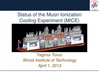
6D MANXA Muon Cooling Demonstration Experiment;How it might fit with MICE. Tom Roberts Muons, Inc. http://muonsinc.com MICE CM17
Outline of this Presentation • 6D MANX is just like MICE, only different • The basic idea of a Helical Cooling Channel • There has been much progress since last time we discussed MANX and MICE • A new magnet design – a helical solenoid – makes it much more buildable and affordable • We now have a solution to the matching problem which puts the input and output along the major solenoid axis • We have made progress in showing the helical cooling channel can be integrated with RF to form a system • Consideration of a different type of experiment using macroparticles • Schedule MICE CM17
6D MANX is just like MICE, only different • Similar, but somewhat different purposes • MICE: demonstrate technology for transverse cooling for a more affordable Neutrino Factory • 6D MANX: foster a Muon Collider revolution for HEP • Energy frontier machine • Precision machine • Our intent is to use extreme cooling so ILC RF structures can be used • Rather different cooling channels • Quite different current status • MICE is of course an approved and established experiment • All major decisions have been made • Engineering is nearing completion • Some construction is complete, installation is imminent • 6D MANX is just starting up • We need to form a collaboration, put organization in place, etc. • We still have major decisions to make • Engineering is in its infancy MICE CM17
6D MANX is just like MICE, only different • Similar goals… • Demonstrate concepts and technology for muon cooling • Similar approach… • Single-particle tracking to demonstrate emittance reduction and validate simulations • Perhaps – possibility of doing a macroparticle experiment • Similar beam… • Few hundred μ per second, 200-300 MeV/c • Similar needs… • Cryogenics, hall space, magnet power, tracking, PID, DAQ, analysis, … • The difference is in the type of cooling channel – MANX is a helical cooling channel, without RF MICE CM17
The Basic Helical Cooling Channel • A combination of a solenoid, helical dipole, and helical quadrupole, all on a common axis • Beam is injected into the HCC along the helix (typically 45° from the solenoid axis) • The solenoid will bend the reference particle along the helix; the helical dipole is oriented to partly cancel this motion • The helix inherently couples transverse and longitudinal modes, such that the transverse-only ionization cooling is re-partitioned into both transverse and longitudinal cooling. • For MANX we are considering two helix periods with period 2 meters and radius 24 cm (plus matching) MICE CM17
The Helical Cooling Channel (HCC)Magnetic Fields Solenoid (Field into the paper) The Helical Dipole and Helical Quadrupole Magnetic Fields. The beam acceptance is 45° into the page, in the light blue circle. Both figures rotate clockwise around the solenoid center as Z increases, thus forming a helix. (This has been extensively analyzed analytically, and there are numerous papers discussing this at http://muonsinc.com) MICE CM17
Progress Since Last Time • The Fermilab Muon Collider Task Force has jumped into MANX with both feet • Their charter includes design and possible construction of the HCC magnet • Their charter includes exploring the possibility of performing MANX at Fermilab (MTA, Meson Test Facility, new facility near the antiproton source) • The MCTF has become part of Fermilab’s new Accelerator Physics Center; muon collider R&D is a top-level component of their charter • The creation of the MCTF and the APC reflect the Fermilab Director’s determination to increase emphasis on accelerator R&D, and his interest in muon colliders MICE CM17
Progress Since Last Time • V. Kashikhin has conceived a completely new magnet design, the helical solenoid (see below) • Much more buildable and affordable than previous design • We now have a preliminary solution to the matching problem (see below) • We now have a preliminary solution to putting RF into the HCC (see below) – not for MANX, but necessary to show the HCC is a viable component of muon facilities • Investigation of macro-particle experiment (see below) • Inherently much less sensitive to beam contamination from pions • Uses much simpler detectors, and fewer of them • Has only limited access to longitudinal motion MICE CM17
Helical Solenoid The helical solenoid consists of a number of ring coils shifted in the transverse plane such that the coil centers follow the helical beam orbit. The current in the rings changes along the channel to obtain the longitudinal field gradients (due to energy loss). This system has a fixed relation between all components for a given set of geometrical constraints. Thus, to obtain the necessary cooling effect, the coil should be optimized together with the beam parameters. For the proper choice of geometry, this system generates the solenoid, helical dipole, and helical quadrupole fields without correction magnets. One can see that the optimum gradient for the helical solenoid is -0.8 T/m, corresponding to a period of 1.6 m. Besides that, the system has other variables, one of which is the inner coil radius. For example, 0.2 m radius increase corresponds to -1 T/m change in the transverse field gradient. At the same time, it has a small influence on the dipole and longitudinal field components which provides another effective way to optimize a transverse gradient. MICE CM17
Helical Solenoid + Matching Helical Sections Total channel length 10 m Total energy 10-15 MJ Z axis muon beam injection LHe absorber inside the channel LHe vessel diameter 1.1 m Outer diameter 1.4 m LHe volume (1.1m dia.) 10 m³ LHe volume absorber (0.5m dia.) 3 m³ Front end 3 m matching section 4 m Cooling Channel Far end 3 m matching section MICE CM17
Incorporate RF cavity in helical solenoid coil • Use a pillbox cavity (but no window this time). • RF frequency is determined by the size of helical solenoid coil. • Diameter of 400 MHz cavity = 50 cm • Diameter of 800 MHz cavity = 25 cm • Diameter of 1600 MHz cavity = 12.5 cm Diameter of RF cavity • The pressure of gaseous hydrogen is 200 atm to adjust • the RF field gradient to be a practical value. • The field gradient can be increased if the breakdown would be • well suppressed by the high pressurized hydrogen gas. MICE CM17
Simulation of High Frequency High Pressurized Cavity in Helical Cooling Channel(3 different HCCs in series, decreasing size) gap • There are gaps in transverse phase space between two segments. • ~20 % of particles is lost in between two segments. • There is no gap in longitudinal phase space. • No radial distribution in the rf field. MICE CM17
Incorporate High Pressurized Cavity in Helical Cooling Channel • Initial e6D is 1.2 × 10⁻⁶ m3. • Final e6D is 2.5 × 10⁻¹⁰ m3. • Cooling factor is 4,000. • The acceptance is smaller by • using a 200 MHz cavity. • Transmission efficiency in a • whole channel is 50 %. • The acceptance of the channel • can be smaller than that in the • 200 MHz cavities. We need more precooler to match the initial beam into the HCC. MICE CM17
Fernow-Neufer Plot Initial point MICE CM17
A Possible Macroparticle Experiment MICE CM17
A Possible Macroparticle Experiment • Currently imagined at the Fermilab MTA • But can barely shoehorn it in – needs more work • Estimate about 1000 mu+ and 800 pi+ per macroparticle (300 MeV/c) • One macroparticle per linac pulse, several pulses per second • Uses otherwise unused linac pulses • Macroparticles are ~2-3 mm wide going in, ~20-30 mm coming out for mu+; very few pi+ come out • While the outgoing macroparticle is quite wide, its mean is well determined • Further simulations are ongoing to complete the analysis of this concept. MICE CM17
Schedule • Possible schedule (Fermilab MCTF): • HCC magnet design – 2008 • HCC prototyping – 2008 • HCC magnet construction – 2009 • HCC ready for MANX – early 2010 • Muon beam into MTA could be comparable schedule, because it uses mostly existing components • Still evaluating muon beam feasibility • Still evaluating macroparticle approach • Beam monitors are sufficiently accurate, and could also be ready • Ultimate schedule will be determined primarily by funding MICE CM17
Conclusions • Putting MANX into the MICE hall now looks much easier than before • 10 meter long cooling channel (3 meters longer than MICE Stage VI) • MANX cooling channel now has coaxial in and out • Solenoid in and out simplifies matching to the MICE spectrometers • The schedule is rather uncertain at this time, as it is primarily driven by funding • MICE Phase 2 and 3 schedule is likewise rather uncertain, also driven primarily by funding • While the Fermilab MCTF is concentrating on performing an experiment at Fermilab, we consider RAL an equally good choice – and the only choice if the macroparticle technique does not pan out. MICE CM17