Download

1 / 12
120 likes | 203 Vues
This project by Paul S. Miyagawa at the University of Manchester focuses on mapping the magnetic field shape inside a solenoid. The main objectives include accurately measuring the field components, correcting for uncertainties, and fitting the data using advanced software. The Mapper machine employs propellor arms with Hall probes to collect data, while the Mapper software processes and corrects the measurements. Simulation is used to analyze raw data, correct for current drift, and apply calibration corrections. Geometrical and Fourier-Bessel fits are employed to refine the measurements. Future plans involve simulating additional effects and incorporating magnetization from the Inner Detector.

E N D
Solenoid Magnetic Field Mapping Objectives Mapper machine Mapper software Simulation Corrections Fitting Future work Paul S Miyagawa University of Manchester
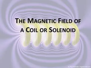
Magnetic Field Shape • z-component dominant near centre of solenoid • r-component more important near ends of coil • field from magnetized iron only 4.5% of total
Objectives • Momentum scale will be dominant uncertainty in lepton mass measurement • Momentum accuracy depends on <equation>, so field at intermediate radii is most important • Need to measure bending power integral of magnetic field to 0.05% accuracy • Bending power defined as Bz – Br z / r
Field Mapper Machine • Two propellor arms which rotate in phi • Carriage slides in z along rails • Up to 25 Hall probes on each arm on both sides • Cross-checks between probes on opposite sides of same arm • Also have cross-checks between arms • Machine measures field inside solenoid before ID installed • Also have 4 NMR probes permanently fixed to solenoid to set overall scale
Field Mapper Software • Convert raw data to physical units • Correct for time drifts in solenoid current • Correct for time drifts in individual Hall probes • Convert to a regular grid • Fit data with two methods: geometrical fit and Fourier-Bessel parametrization • Use fits to correct normalization and alignment
Simulation of Raw Data • Field calculated from solenoid of expected dimensions • Magnetization due to magnetic material from outside Inner Detector • Random walk with time for solenoid current and Hall probe measurements • Random errors for each measurement
Correction for Current Drift • Average B-field of 4 NMR probes used to calculate “actual” solenoid current • Scale all measurements to a reference current (7600 A) • Effect of random walk in current removed
Correction for Hall Probe Drift • Mapping machine regularly returns to fixed calibration positions • Near coil centre to calibrate Bz • Near coil end for Br • No calibration of Bphi • Each channel is calibrated to a reference time (beginning of run) • Scaling factors from calibration points used to determine scalings for measurements between calibrations
Geometrical Fit • Sum of simple fields known to obey Maxwell’s equations • Long-thin coil (5 mm longer, 5 mm thinner than nominal) • Short-fat coil (5 mm shorter, 5 mm fatter) • Four terms of Fourier-Bessel series (for magnetization) • Use Minuit for chi2 fit to data
Fourier-Bessel Fit • General fit able to describe any field obeying Maxwell’s equations • Needs large number of parameters • Poor fit indicates measurement errors rather than incorrect model • Main contribution to field found from measurements on cylinder surface, i.e., large radii • Measurements at smaller radii needed at ends of cylinder
Future Plans • Simulate other effects • Geometrical misalignments • Systematic measurement errors • Readout errors, e.g., missing measurements • Mapper machine scheduled to take data in late February 2006 • Add magnetization due to magnetic materials in Inner Detector