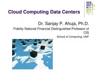
Cloud Computing Data Centers
Cloud Computing Data Centers. Dr. Sanjay P. Ahuja, Ph.D. Fidelity National Financial Distinguished Professor of CIS School of Computing, UNF. Warehouse-Scale Data Center (WSC) Design. Warehouse-Scale Data Center Design.

Cloud Computing Data Centers
E N D
Presentation Transcript
Cloud Computing Data Centers Dr. Sanjay P. Ahuja, Ph.D. Fidelity National Financial Distinguished Professor of CIS School of Computing, UNF
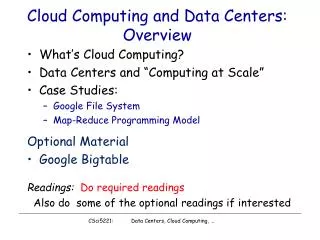
Warehouse-Scale Data Center Design • The cloud is built on massive datacenters. Datacenters as large as a shopping mall can house 400,000 to 1 million servers. These data centers are built on economies of scale, i.e. the larger the datacenter, the lower the operational cost. • The network cost to operate a small data center is about 7 times greater and storage costs about 5.7 times greater than the costs to operate a large data center. • Most datacenters are built with commercial off the shelf (COTS) components. A COTS server consists of a number of processor sockets, each with a multicore CPU and its internal cache hierarchy, local and shared DRAM, and a number of directly attached disk drives (DASD). • The DRAM and the DASD within the rack are accessible through first-level rack switches and all resources in all racks are accessible via a cluster-level switch. • Example: a data center with 2000 servers, each with 8 GB DRAM and four 1 TB disk drives. Each group of 40 servers is connected through a 1 Gbps link to a rack-level switch that has an additional eight 1 Gbps ports for connecting the rack to the cluster-level switch. .
Warehouse-Scale Data Center Building Blocks . Typical elements in warehouse-scale systems: 1 server (left), 7´ rack with Ethernet switch (middle), and diagram of a small cluster with a cluster-level Ethernet switch/router (right).
Warehouse-Scale Data Center: Network Fabric • Choosing a networking fabric for WSCs involves a trade-off between speed, scale, and cost.1-Gbps Ethernet switches with up to 48 ports are essentially a commodity component, costing less than $30/Gbps per server to connect a single rack. • However, network switches with high port counts, which are needed to tie together WSC clusters, have a much different price structure and are more than ten times more expensive (per 1-Gbps port) than commodity switches. • As a result of this cost discontinuity, the networking fabric of WSCs is often organized as the two-level hierarchy depicted in the previous figure. • For example, a rack with 40 servers, each with a 1-Gbps port, might have eight 1-Gbps uplinks to the cluster-level switch, corresponding to an oversubscription factor between 5 for communication across racks. • Generally, intra rack connectivity is often cheaper than inter rack connectivity.
Warehouse-Scale Data Center: Storage Hierarchy . Figure shows a programmer’s view of storage hierarchy of a typical WSC. A server consists of a number of processor sockets, each with a multicore CPU and its internal cache hierarchy, local and shared DRAM, and a number of directly attached disk drives. The DRAM and disk resources within the rack are accessible through the first-level rack switches (assuming some sort of remote procedure call API to them), and all resources in all racks are accessible via the cluster-level switch.
Warehouse-Scale Data Center: Cooling System • CRAC units (CRAC is a 1960s term for computer room air conditioning) pressurize the raised floor plenum by blowing cold air into the plenum. This cold air escapes from the plenum through perforated tiles that are placed in front of server racks and then flows through the servers, which expel warm air in the back. • Racks are arranged in long aisles that alternate between cold aisles and hot aisles to avoid mixing hot and cold air. • Eventually, the hot air produced by the servers re-circulates back to the intakes of the CRAC units that cool it and then exhaust the cool air into the raised floor plenum again. • CRAC units consist of coils through which a liquid coolant is pumped; fans push air through these coils, thus cooling it. A set of redundant pumps circulate cold coolant to the CRACs and warm coolant back to a chiller or cooling tower, which expel the heat to the outside environment. • Typically, the incoming coolant is at 12–14°C, and the air exits the CRACs at 16–20°C, leading to cold aisle (server intake) temperatures of 18–22°C. .
Warehouse-Scale Data Center: Quantifying Latency, Bandwidth, and Capacity
Warehouse-Scale Data Center: Quantifying Latency, Bandwidth, and Capacity • The next figure attempts to quantify the latency, bandwidth, and capacity characteristics of a WSC. • We assume a system with 2,000 servers, each with 8 GB of DRAM and four 1-TB disk drives. Each group of 40 servers is connected through a 1-Gbps link to a rack-level switch that has an additional eight 1-Gbps ports used for connecting the rack to the cluster-level switch (anoversubscription factor of 5). • The graph shows the relative latency, bandwidth, and capacity of each resource pool. For example, the bandwidth available from local disks is 200 MB/s, whereas the bandwidth from off-rack disks is just 25 MB/s via the shared rack uplinks. On the other hand, total disk storage in the cluster is almost ten million times larger than local DRAM. • A large application that requires many more servers than can fit on a single rack must deal effectively with these large discrepancies in latency, bandwidth, and capacity.
Container Data Center Design • Container-based datacenters go one step beyond in-rack cooling by placing the server racks into a standard shipping container and integrating heat exchange and power distribution into the container as well. • Similar to full in-rack cooling, the container needs a supply of chilled water and uses coils to remove all heat from the air that flows over it. • Air handling is similar to in-rack cooling and typically allows higher power densities than regular raised-floor datacenters. Thus, container-based datacenters provide all the functions of a typical datacenter room (racks, CRACs, cabling, lighting) in a small package. • Like a regular datacenter room, they must be complemented by outside infrastructure such as chillers, generators, and UPS units to be fully functional. • The container-based facility has achieved extremely high energy efficiency ratings compared with typical datacenters today. E.g. Google’s container based datacenter. .