Motherboard Essentials for PC Hardware Setup
Explore physical form factors, components, chipsets, and controllers of motherboards, essential for PC hardware configuration. Learn about various types of motherboard components and how they impact computer performance.

Motherboard Essentials for PC Hardware Setup
E N D
Presentation Transcript
PC Hardware Basic Guide Module 4 - Motherboard
Module 4 - Motherboard • Overview • It is a Printed Circuit Board that performs the key functions to enable smooth running of the computer. • Lesson Covered in this Module • Motherboards • Standard Expansion Buses
Lesson 1 - Motherboards • Introduction • Motherboard is a Printed Circuit Board which possesses different components for various purposes. It contains • CPU • BIOS, • Memory • I/O ports • External I/O connectors • I/O controllers • Expansion slots • Chipsets.
Module 4 - Motherboard • Topics Covered in this Lesson • Physical Form Factors • Motherboard Components • System Chipsets and Controllers • CMOS Settings • Power On Self Test (POST) • System Resources
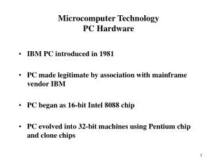
Topic 1 - Physical Form Factors • Personal Computer – Extended Technology (PC-XT) • Introduced by IBM, 8088 microprocessor was used. • It has socket for the processor and chips
Topic 1 - Physical Form Factors • AT and Baby AT • To overcome the problem created by AT Form factor, the Baby AT form factor was introduced. • Baby AT is designed to hold the peripheral devices like keyboard, video and mouse. • It could not accommodate the combination of processor, heat sink and fan. Cooling
Topic 1 - Physical Form Factors • ATX and Micro ATX form factor • Here expansion slots were placed on separate riser cards. • It provides software controlled shut down and power up. • Micro ATX form factor • More space for I/O connectors was provided at the rear end.
Topic 1 - Physical Form Factors • LPX and Mini-LPX • It has sound and video to be integrated on to the motherboard. • It is not suitable for upgrading and offers poor cooling. • NLX • Small in size • Suited for low profile desktop cases
Topic 2 - Motherboard Components • The major components of the motherboard • Processor socket or slot • Chipset • Super I/O chip • BIOS • SIMM/DIMM sockets • Bus slots
Topic 2 - Motherboard Components • Chipset and Functions • Different chips integrated to a single chip called the chipset. • North bridge and South bridge was introduced to the motherboard with PCI slots. • The south bridge controls the slower I/O components like the Serial ports, USB ports and the IDE.
Topic 2 - Motherboard Components • The new technology, Intel Hub Architecture (IHA) uses two chips called hub controllers. • The hub controllers are • Graphics and Memory Controller Hub (GMCH) • I/O Controller Hub (ICH) • The chipset determine • The voltage provided to the processor • Number of processors that can be supported • The speed of the processor • The different memory modules that are supported • Bus speed • The different expansion bus that are supported • Power Management
Topic 3 - System Chipset and Controllers • The system chipset and controllers are the intelligence of the motherboard. • Chipset has a effect on the quality, feature set and speed of the computer. • Controllers found on motherboards • The system chip • The keyboard controller • The super I/O chip • Additional built-in controllers
Topic 3 - System Chipset and Controllers • Qualities and Functions of Chipset • Chipset Processor Support • Support for Processor Class and Optimization - Supports one generation of processors • Support for Processor Speed - Fast processors need chipset control circuitry that has the capacity to manage them. • Support for Multiple Processor - Chipset support the capability for building motherboards with two or four processors on them.
Topic 3 - System Chipset and Controllers • Chipset Cache Support - The cache stores recent memory accesses by the processor • Size of Secondary Cache - Chipsets support cache of 256KB or 512 KB. • Type of Secondary Cache - three major kinds of cache, Asynchronous, Synchronous burst, Pipeline burst. • Write Policy of Secondary Cache - A write-through cache and a write back cache. • Cacheability of System Memory - The amount of cacheable memory is dependent on the chipset control circuitry and the amount of tag RAM on the board.
Topic 3 - System Chipset and Controllers • Chipset Memory Support - The chipset determines several permissible features of the memory • Support for Maximum Memory-Determines the maximum quantity of RAM a system can have on the motherboard • DRAM Technology - Regulates whether motherboard can make use of FPM, EDO, BEDO, or SDRAM memory. • Support for DRAM Packaging and Size - Two main types of memory packages are, single in-line memory module (SIMM) and dual in-line memory module (DIMM). • Support for Parity and Error Correction - Error correction logic is offered as part of the memory control circuits of the chipset.
Topic 3 - System Chipset and Controllers • Chipset Peripheral and I/O Bus Control - Most recent computers use two buses, (ISA) bus and l component (PCI) bus. • Bus Types - The chipset determines what type of buses the system can support. • Bus Bridges – Bridge is used for connecting together devices on two different buses. • IDE/ATA Hard Disk Controller - All motherboards have integrated into them support for four IDE hard disks • DMA Controller and DMA Mode Support – Process of transferring information directly to and from memory with no interference of the processor.
Topic 3 - System Chipset and Controllers • Interrupt Controller • USB Support • AGP Support • Plug and Play
Topic 3 - System Chipset and Controllers • Chipset Power Management Support – Works through a number of BIOS settings that determine when to shut down different parts of the computer • Energy Star • Advanced Power Management • Display Power • Management Signalling • System Management Mode • Hard Disk Spindown
Topic 3 - System Chipset and Controllers • Super I/O Controller Chip super I/O controller handles three ports • Serial Port Control – controls the serial ports, UART • Parallel Port Control – manages and controls the parallel port • Floppy Disk Drive Control – supports the Floppy Disk Drive and floppy based tape drives
Topic 3 - System Chipset and Controllers • Processor • Two major components • Arithmetic and Logic Unit (ALU) – performs Arithmetic and Logic Operations • Control Unit (CU) – provides the control signals for performing different operations. • Cache Memory • It is high speed storage memory made of Static RAM (SRAM). • Two types of cache memory are L1 or the internal cache and L2 cache or the external cache.
Topic 3 - System Chipset and Controllers • I/O Ports • Each device connected to a computer uses I/O port address. • Functions of I/O address • Sending commands to the peripheral device • Receiving the status of the device whether it is idle or busy • Send and receive data • Configure the device for interrupts • Bus Speed • The speed of the bus refers to the amount of the data that can be transferred across the bus.
Topic 3 - System Chipset and Controllers • Some of the bus types are, • Front side Bus - The bus speed in general refers to the speed of the Front Side Bus (FSB). • AGP Bus – It connects the video card to the memory and the CPU. • Back side Bus – It connects the processor to the L2 Cache
Topic 3 - System Chipset and Controllers • Memory bus – It connects the north bridge to the memory. • IDE or ATA bus – It connects the south bridge to the disk drives. • PCI Bus – It connects the PCI slots to the south bridge.
Topic 3 - System Chipset and Controllers • Jumpers • It is a small connector which can be placed between two pins to make electrical connections. • DIP switch • The dual inline package switch is a small block provided with a lever.
Topic 4 - CMOS Settings • CMOS BIOS ROM • Stores the basic system configuration. The four major components of BIOS are • POST • Bootstrap Loader • CMOS Setup • BIOS ROM
Topic 4 - CMOS Settings • CMOS Battery • Battery is used to power up the Real time Clock Chip. • This chip maintains the system date and time. • System Configuration • The BIOS should find an operating system on a hard disk or floppy disk drive to start the computer. • Starting the Setup Program • The settings made in the BIOS setup program are stored in the nonvolatile RAM of the CMOS chip.
Topic 4 - CMOS Settings • Step-by-Step CMOS/BIOS Configuration • From the CMOS setup menu, select the menu point to examine or change setting and choose Standard CMOS setup to begin.
Topic 4 - CMOS Settings • From the standard CMOS configuration screen you can set Date, Time, Hard drives connected to the IDE interface, Floppy disk drive types for drives
Topic 4 - CMOS Settings • Advanced CMOS Configuration • Here, you can perform the Number Lock setting, keyboard repeats speed, type of video, settings for cache memory, and other special features.
Topic 4 - CMOS Settings • Recommended Advanced CMOS Settings • Depending on the BIOS version, you have to press the ESC key, to return to the main menu
Topic 4 - CMOS Settings • Power Management Configuration • After a user defined period of inactivity of devices like the monitor, the hard drive, or the CPU will go into different low power modes. • Standby mode • Suspend mode
Topic 4 - CMOS Settings • Built-In Ports/Peripherals Setup • It can enable or disable ports which built in new systems.
Topic 4 - CMOS Settings • Security/Passwords • Two types of passwords are • One must be entered to allow any use of the system • Another one must be entered to allow access to the BIOS/ CMOS setup • Saving and Recording BIOS/CMOS Settings • BIOS allows you to save the changes and it will reject the changes that happen accidentally. • Record the critical BIOS settings
Topic 4 - CMOS Settings • BIOS Upgrades • Change the physical chip or to change its contents with software • Flash BIOS Upgrade • Install the BIOS upgrade loader and BIOS image to a floppy disk • Incorrect CMOS Configuration • Restart by using the BIOS Setup auto-configure options, double-check drive configurations, save changes, and restart.
Topic 4 - CMOS Settings • Incorrect Flash BIOS or Failed Update • If the update can't be installed, the motherboard might have jumpers that write-protects the flash BIOS. • Clearing the BIOS Password • It can be cleared by using a CMOS jumper that is present in the motherboard.
Topic 5 - Power On Self Test (POST) Error codes • Some main functions of BIOS during POST • Helps to start the Operating System. • Check for the integrity of the BIOS code • Some error beeps • No beep - Power supply or system board problem • 1 long, 1 short beep - System board problem • Long beeps - 3270 keyboard card • Some error codes • 100 to 199 - System board • 200 to 299 - Memory • 300 to 399 - Keyboard
Topic 6 - System Resources • System resources are components that are required to communicate between the hardware components in a PC. • Interrupt Request Channels (IRQ) • Hardware devices use IRQ signal to the processor • There are 16 IRQ channels .
Topic 6 - System Resources • The snapshot shows the different IRQ channels associated with different devices.
Topic 6 - System Resources • Direct Memory Access (DMA) channels • Here the data is transferred between the peripheral device and the memory without the intervention of the CPU. • Devices connected to serial and parallel port do not use DMA channels • I/O Port Address • It is an interface present in a PC to connect devices • The port address ranges from 0000h to FFFFh
Topic 6 - System Resources • The snapshot displays the I/O address range used by different devices
Topic 6 - System Resources • Checking for Resource Availability • For Windows 3.x or MS-DOS, the resource settings can be verified by using the MSD command present in the DOS directory. • For Windows 2000 or Windows XP, follow the step given below to identify the resources used by the different devices Click Start ProgramsAccessories System Tools-> System Information
Lesson 2 - Standard Expansion Buses • Introduction • The expansion slots are used to enhance the features of the PC. • The expansion slots can hold expansion cards like the sound card, VGA card, AGP card, Network card etc • There are different types of expansion slots. Industrial Standard Architecture (ISA) bus • Micro Channel Architecture (MCA) Bus • Extended ISA (EISA) Bus • Video Electronics Standard Association (VESA) Bus • Peripheral Component Interconnect (PCI)Bus • Peripheral Component Interconnect – X • Accelerated Graphics Port • Audio Modem Raiser and Communication Network Raiser
Lesson 2 - Standard Expansion Buses • Topics Covered in this Lesson • PC Bus • Industrial Standard Architecture (ISA) Bus • Micro Channel Architecture (MCA) Bus • Extended ISA (EISA) Bus • Video Electronics Standard Association (VESA) Bus • Peripheral Component Interconnect (PCI) Bus • Accelerated Graphics Port • Audio Modem Raiser and Communication Network Raiser
Topic 1 – PC Bus • PC bus is an 8 bit expansion slot to connect 8 bit expansion cards.
Topic 2 - Industrial Standard Architecture (ISA) Bus • ISA bus is a 16 bit slot present in 80286, 80386, 80486 and Pentium systems. • The ISA card is configured through jumpers or switches
Topic 3 - Micro Channel Architecture (MCA) Bus • Bus Mastering - The components that can take control over the bus are called bus masters. • Features of MCA • It is a 16 or 32 bit bus created by IBM • Supports bus mastering • Operates at 10-12 MHZ • Can be configured through software • Has Lower Noise Level
Topic 4 - Enhanced ISA • It is a 32 bit bus. • Capable of using multiple bus mastering devices. • Compatible 8 bit PC bus, 16 bit ISA bus. • Software setup capability for boards
Topic 5 - Video Electronics Standard Architecture (VESA) bus • It is a 32 bus. • It is used to connect video cards, I/O cards and multimedia expansion cards • Disadvantages of the VESA • 80486 dependence • Limited number of slots • No bus mastering • Boards are configured through jumpers
Topic 6 - Peripheral Component Interconnect (PCI) bus • PCI • Operates at a speed of 33 MHz or 66 MHz • It is a 64 bit bus • Communicates with processor using a bridge circuit. • PCI-X • Operates at 133 MHz bus speed • Offers 64 bit Band width • Supports 1 GB/Sec data transfer rate • Supports efficient bus operation • Provides backward Compatibility
Topic 7 - AGP Bus • It is designed for connecting video cards. • PCI bus with 2.1 version at 66MHZ is the basis for AGP slot. • It supports a new technique called texture cache.