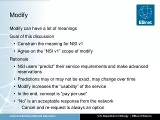
Modify RF Ion Source
T.p. gas. gas. Modify RF Ion Source. Beam from ion source emerges with low energy Gas leakage from ion source canal fills low energy end of accelerator Gas scattering degrades ion source brightness Solution: Add recirculating turbopump. new. old. From the work of Roland Szymanski.


Modify RF Ion Source
E N D
Presentation Transcript
T.p. gas gas Modify RF Ion Source • Beam from ion source emerges with low energy • Gas leakage from ion source canal fills low energy end of accelerator • Gas scattering degrades ion source brightness • Solution: Add recirculating turbopump new old From the work of Roland Szymanski
Modify Accelerator Column • Remove corona needles and replace with resistors • (Have now increased brightness by a factor of 10) • So need to design a system optimised for a flux peaked beam… • High demagnification!
1970 Russian quadruplet Dx=Dy=30 1980 Oxford high excitation triplet Dx=25 Dy=90 1998 Leipzig separated quadruplet Dx=80 Dy=80 Dx=67Dy=71 1998 CSIRO/MARC high excitation quintuplet Dx=240Dy=50 2000 Oxford separated triplet 2001 New system ? Dx=Dy=200 Selected new quadrupole systems
CSIRO quintuplet system Leipzig two stage system • Strong demagnification in a long system • Strong demagnification in a short system, 80 mm WD • Very intense beam spot into 1 mm 1 2 5 4 3
1.2 mm x 0.9 mm at 0.1 nA 1.8 mm at 8 nA 12.7 mm 12.7 mm Resolution Versus Beam Current: CSIRO/MARC quintuplet system 1.3 mm at 0.5 nA 3100 pA/mm2 ! 2.0 mm at 10 nA 3 mm at 20 nA Accelerator brightness = 1.2 pA.mm-2.mrad-2.MeV-1 CSIRO-GEMOC Nuclear Microprobe From the work of Chris Ryan
Leipzig New Ox Oxford triplet CSIRO 5 MP2 Bochum Future Developments Conclusion: To break through the 1 micron wall • Install heavier magnetic shielding! But be sure to clean off DC fields (10 nT). • Don’t worry about chromatic and spherical aberration, they are not a severe as first though because of flux peaking (<0.1 mm) • Make brighter ion sources by small tweaks, even a factor of 10 is helpful (x1/3) • Install an optimised system for a strongly flux peaked accelerator, this will have a large demagnification (of necessity a high excitation system) (M-1 > 200) • Need more radical lens design to reduce working distance and increase fields (40 mm) • Apply the new system to some interesting problems! (< 0.1 mm resolution)
Poletip N S z N S Spherical Aberration: A closer look • The TFF model also revealed the need for careful attention to the field overlap between adjacent lenses • Must have a linear field gradient as a function of beam direction to minimise aberrations • Need to shape pole ends to achieve this Pole tip N S ? z S N