Superstructure
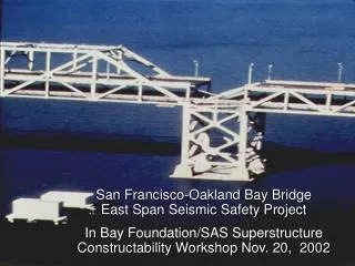
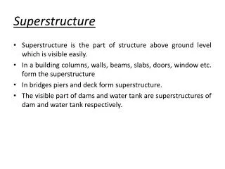
Superstructure. Superstructure is the part of structure above ground level which is visible easily . In a building columns, walls, beams, slabs, doors, window etc. form the superstructure I n bridges piers and deck form superstructure.

Superstructure
E N D
Presentation Transcript
Superstructure • Superstructure is the part of structure above ground level which is visible easily. • In a building columns, walls, beams, slabs, doors, window etc. form the superstructure • In bridges piers and deck form superstructure. • The visible part of dams and water tank are superstructures of dam and water tank respectively.
Types of loads on superstructures • To get safe structures at the same time without ignoring economy of the structure, it is necessary to estimate the various loads acting suitably. • Indian standard code IS: 875–1987 specifies various design loads for buildings and structures. They have grouped various loads as under: • Dead loads • Imposed loads • Wind loads • Snow loads • Earthquake loads • Special loads • Details of earthquake load is covered in IS: 1893 – 1984 which should be considered along with other types of loads given in IS-875. • The code also gives various load combinations to be considered in the design.
Dead loads • The dead load in a building comprises the weight of roofs, floors, beams, columns, walls, partition walls etc. which form permanent part of the building. • It is to be found by working out volume of each part and then multiplying with unit weight. • Unit weight of various materials are listed in part-I of IS: 875. • Unit weights of some of the common materials are presented in Table
Imposed loads (IL) • The loads which keep on changing from time to time are called as imposed loads. • Common examples of such loads in a building are the weight of the persons, weights of movable partition, dust loads and weight of furnitures. • These loads were formerly known as live loads. • These loads are to be suitably assumed by the designer. • It is one of the major load in the design. • The minimum values to be assumed are given in IS 875 (part 2)–1987. • It depends upon the intended use of the building. • These values are presented for square metre of floor area.
The code gives the values of loads for the following occupancy classification:- • Residential buildings–dwelling houses, hotels, hostels, boiler rooms and plant rooms, garages. • Educational buildings • Institutional buildings • Assembly buildings • Business and office buildings • Industrial buildings, and • Storage rooms. • The code gives uniformly distributed load as well as concentrated loads. • The floors are to be investigated for both uniformly distributed and worst position of concentrated loads. • The one which gives worst effect is to be considered for the design but both should not be considered to act simultaneously.
In a particular building, imposed load may change from room to room. • For example in a hotel or a hostel building the loads specified are,
Wind loads • The force exerted by the horizontal component of wind is to be considered in the design of buildings. • It depends upon the velocity of wind and shape and size of the building. • Complete details of calculating wind load on structures are given in IS-875 (Part 3) -1987 • Brief idea of these provisions are given below: • Using colour code, basic wind pressure ‘Vb’ is shown in a map of India. • Designer can pickup the value of Vb depending upon the locality of the building. • To get the design wind velocity Vzthe following expression shall be used: Vz= k1 k2 k3 Vb
Where • k1 = Risk coefficient • k2 = Coefficient based on terrain, height and structure size. • k3 = Topography factor • The design wind pressure is given by pz= 0.6 Vz^2 • where pzis in N/m2 at height Z and Vzis in m/sec. • Up to a height of 30 m, the wind pressure is considered to act uniformly. • Above 30 m height, the wind pressure increases.
Earthquake Loads • Earthquake shocks cause movement of foundation of structures. • Due to additional forces develop on super structure. The total vibration caused by earthquake may be resolved into three mutually perpendicular directions, usually taken as vertical and two horizontal directions. • Themovement in vertical direction do not cause forces in superstructure to any significant extent. • But movement in horizontal directions cause considerable forces. • IS: 1893– 1984 gives the details of such calculations for structures standing on soils which will not considerably settle or slide appreciably due to earthquake. • The seismic accelerations for the design may be arrived at from seismic coefficients, which is defined as the ratio of acceleration due to earthquake and acceleration due to gravity. • For the purpose of determining the seismic forces, India is divided into five zones.
Depending on the problem, one of the following two methods may be used for computing the seismic forces • Seismic coefficient method • Response spectrum method • The details of these methods are presented in IS 1983 code and also in National Building Code of India. • After the Gujarat earthquake (2000) Government of India has realized the importance of structural designs based on considering seismic forces and has initiated training of the teachers of technical institution on a large scale.
Load Combination • A judicious combination of the loads is necessary to ensure the required safety and economy in the design keeping in view the probability of • Their acting together • Their disposition in relation to other loads and severity of stresses or deformations caused by the combination of various load.
Types of construction • Load bearing construction. • Load from roof slabs and floors are transmitted through walls to firm soil below ground. • Therefore, the walls of upper storey will have less thickness than walls of upper storeys,the carpet area reduces on ground floor compared to upper floor. • This type of construction is adopted at places where hard strata is available at shallow depths. • It is suited for simple building of 2 storey construction. • Materials used are stone, brick bound together with cement or lime mortar. • For floor and roof slabs RCC can be used • The structural elements such as beams rest directly on walls. • The floor rest on beams.
Framed constructions • If reinforced cement concrete or steel frame consisting of columns, beams, slabs are built first and walls are built only to enclose the area, the load transfer is mainly by beams and columns walls carry only self weight. • These walls serve as filler materialand do not contribute to load transfer. • Such structures are called framed structures. • Load from beams is transferred to columns which transfer to foundation footing and ultimately the load is transferred is taken up by soil on larger area.
3) Composite Structures. • For construction of large span buildings like workshops, warehouses it is not desirable to strictly follow only one type of system, that is load bearing versus framed construction. • In such building the exterior walls are load bearing and intermediate supports are in form of RCC columns. • Thus it forms the composite structures • Floors and roofs are supported on load bearing walls as well as inner columns.