Understanding Internet Protocol: Key Features and Functionality
This article provides an overview of the fundamental features of Internet Protocol (IP) as outlined in the specification. It highlights IP's characteristics such as its unreliable, connectionless delivery system and best-effort service without guarantees. The document elaborates on the IP header structure, including fields like version, header length, type of service, total length, and fragmentation. Additionally, the role of the Internet Control Message Protocol (ICMP) in managing errors and network issues is discussed, along with the critical aspects of IP routing and datagram handling.

Understanding Internet Protocol: Key Features and Functionality
E N D
Presentation Transcript
Internet Protocol 2005. 3. 16 백 일 우
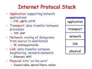
Basic Features • Unreliable, connectionless Delivery • Best Effort Service • No Guarantee that IP datagram successfully get to its Dest. • When Something wrong, IP runs A simple error Handling Algorithm • ICMP : Congestion, Redirect, Packet Arrived or Not • Each Datagram is Handled Independently, so Delivered out of order • Fragmentation/Reassembly For supporting network Interface which has variable frame sizes
IP Header • Version • Only V4 and V6 are used • Other is not used
IP Header • Header Length • Range is 4bits, so it can present values 0~15 • Specifies the length of the IP packet header in 32 bit words • Header Length = Real Value Times(*) 4byte(32bits) • If value is 5, Real Length is 5*4 = 20 (bytes) • Header Length valid Range • 5 ~ 15 • Minimun 20 ~ Maximum 60 (5*4 ~ 15*4) • It is only can be presented by a multiple of 4 • So, If Can not be presented by 4-multiple, Must add ‘Padding’ to be type of 4-multiple
IP Header • Type of Service (TOS) • Specifies the parameters for the type of service requested • The parameters may be utilized by networks to define the handling of the datagram during transport • Precedence • Basically Setted by 000, the others is not allowed • Delay • 0 : Normal Delay, 1: Low Delay • 1 for sound, movie and Logon request • Throughput • 0 : normal Throughput, 1: High throughput • If 1, a Router select the way which has the best BW
IP Header • Precedence
IP Header • Reliability • 0 : normal Reliability, 1: High Reliability • As so many traffics are driven to some router, the router decide which packet is less significant with Reliability Field, and Drop it. • Cost • 0 : normal Cost, 1 : Low Cost • Decide which way is more reasonable, checking this field. • Reserved • Last field is always set by 0 (MBZ : Must Be Zero), So routers ignore this field. • Total Length • Contains the length of the datagram (16 bits) – MAX : 65535 bytes • IP header + IP Payload • MAX(65535 bytes) possible, but most link-Layer will fragment this
IP Header • Identification (16bits) • Used to identify the fragments of one datagram from those of another. • Flags • R, Reserved. 1 bit. Should be cleared to 0. • DF, Don’t Fragment, 1bit. • Controls the fragmentation of the datagram • 0 : Fragment if necessary, 1 : Nope! Fragment • MF,More fragments. 1 bit. • Indicates if the datagram contains additional fragments • 0 : This is the last Fragment, 1: More Fragments follows after this • Fragment Offset (13 bits) • Used to direct the reassembly of a fragmented datagram
001 123 0000 123 2,300 bytes IP Header – Fragmentation More Fragments follow <Identification & Fragmentation> Identification 1000 001 123 Last Fragment 2000 000 123 MTU = 2,300 MTU = 1,000 ROUTER <Fragment Offet 역할> B C D A IP Header IP Header PayLoad A까지 IP Header PayLoad B까지 IP Header PayLoad C까지 IP Header PayLoad D까지
IP Header H7 R3 H8 H1 H2 H3 Network 4 (Point-to-Point) Network 2(Ethernet) Network 2(Ethernet) R1 R2 Ethernet MTU : 1500 FDDII MTU : 4500 Suppose PtoP MTU is 532(included Header) H1 datagram : 1420 H4 Network 3(FDDI) H5
Start of header Start of header Start of header Start of header Iden = A Iden = A Iden = A Iden = A 1 0 1 0 Offset = 0 Offset = 0 Offset = 1024 Offset = 512 Rest of Header Rest of Header Rest of Header Rest of Header 512 data bytes 376 data bytes 1400 data bytes 512 data bytes IP Header • 1400 bytes split into pieces of 512 bytes > 1400 = 512 + 512 + 376
IP Header • TTL (Time To live) – 8bits • A timer field used to track the lifetime of the datagram. When the TTL field is decremented down to zero, the datagram is discarded • Protocol – 8bits • This field specifies the next encapsulated protocol
IP Routing - Intro • Forwarding • That is, Send the packet which is sent from outside to reasonable path, checking the routing table • Routing • That is, Configuring the routing table to make the router send the packet to the reasonable path • Routing Table Contains.., • Destination IP addr • This can be either a complete host addr, or a network addr, as specified by the flag field • IP addr of a next-hop router • Flags • One specifies whether Dest IP addr is Addr of Network or Host • Another says whether the next-hop router field is really a next-hop router or a directly connected interface.
IP Routing - Intro Minimal Encapsulation
IP Routing - Intro • Key Points from previous examples • All hosts and routers in this example used a default route. Indeed, most host and some routers can use a default route for everything other than destinations on Local networks • The Destination IP addr in the datagram never changes. All the routing decision are based on this destination address • In previous Example, Both Ethernets encapsulated header containing the next-hop’s ethernet address, but the SLIP link did NOT • The Ethernet addresses are normally obtained using ARP
Subnetting & Subnet Mask • Purpose • For efficient IP address usage, and Reducing the size of routing tables • Subnet • One network Number of IPs can be assigned in many physical Networks • Conditions • Seen from outside as if It were single Network • That is, Router can select one path for them • Campus can be good example • All nodes on each subnet must be configured with same subnet mask to share Just one network number • Subnet Mask • IP organization Could be more specific • Network and host to Network, subnet, and host
Network Number Host Number Class B 111111111111111111111 00000000 Subnet mask(255.255.255.0) Network Number Subnet ID Host ID Subnetted Address Subnetting & Subnet Mask Subnet Mask : 255.255.255.128 Subnet Number : 128.96.34.0 128.96.34.15 128.96.34.1 H1 R1 • H1 -> H2로 보내고자 한다면, • And 연산을 한다 • 결과 : 128.96.34.128 • H1의 서브넷과 일치 않함!! • H1과 H2는 다른 서브넷상에 있다는 것을 알수 있음 128.96.34.130 Subnet Mask : 255.255.255.128 Subnet Number : 128.96.34. 128 128.96.34.139 H3 R2 H2 128.96.33.1 128.96.33.14
Subnetting & Subnet Mask • H1 -> H2 • R1: 128.96.34.139 AND 255.255.255.128 • Result : 128.96.34.128 • Compare 128.96.34.0 with 128.96.34.128 -> X • Compare 128.96.34.0 with next entry • Through this works, R1 forward to H2 using interface 1 <Subnetted Forwarding Table>
Question • 패킷 단편화후 그 단편화된 Datagram들이 꼭 순서에 맞게 도착하지 않음 . • Host에서는 맨 마지막 조각이 오고 나서 재조립을 시작하는가. • Flag M = 0 이라는 마지막 조각이 먼저 오게 되면, 언제까지 기다려야 되나.