Advanced Counting House Network to Surface Sector with ACM Connections and Data Sampling
Explore the cutting-edge technologies used in the counting house network, from FECs based on microTCA chassis to Optical Fiber and White Rabbit Ethernet data distribution. Learn about Versatile GBT Link technology and Analog Interface in the radioactive zone.

Advanced Counting House Network to Surface Sector with ACM Connections and Data Sampling
E N D
Presentation Transcript
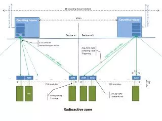
18 counting house (sector) Network to the surface 878m Counting house Counting house Network to the surface Sector n Sector n+1 FEC 2 x 219 ACMconnections per sector Acq./Ctrl. Data Sampling clockTriggering Digital link: optical fiber max length: ~450m 2m ... ... … … ... ACM … … ... ACM ACM ACM ACM 5m 219 modules 219 modules TBM 1 ACM/ TBM ~21000 ACMs Analog interf.5 m max. Radioactive zone
Optical fiber White Rabbit Ethernet data/clock distribution Counting house FEC FEC based on microTCA chassis Optical fiber Versatile GBT Link Up to 4.8 Gbit/s ACM GBT Slave Card Copper E-link lines 80,160 ,320Mbit/s FE module based on FPGA/ASIC FE FE ADC ADC ADC Cable with analog signal from sensor FE directly connected to ADC. Probably via FMC connector TBM TBM Sensor Sensor Sensor
400Mhz 400Mhz GBT Master GBT Slave Versatile link 3.8Ghz Master Transmitter 300 Clk cycles Master Receiver Receiver Oversampling
9th 10th Transmitted clock Delay = 10 Delay = 10 Delay = 10 Delay = 10 Received clock Delay = 10 Delay = 10 Delay = 10 Delay = 11