RF Synchronization Activity at SPARC
This document summarizes the RF synchronization and phase stability specifications for the SPARC project, presented during the EUROFEL DS3 Meeting at CEA-Saclay on May 17, 2005. It details the phase stability requirements for SPARC Phase I and II, the RF distribution schematic, and the mechanisms for phase monitoring and correction of both slow and fast phase variations. Additionally, it discusses measurements of klystron phase noise, the ongoing development of a fast intra-pulse phase-lock system to actively mitigate fast phase jitter, and concludes with insights on the expected phase jitter improvements in SPARC.

RF Synchronization Activity at SPARC
E N D
Presentation Transcript
RF Synchronization Activity at SPARC • Gallo • and • D. Alesini, M. Bellaveglia, R. Boni, G. Di Pirro, A. Drago, A.Ghigo • P. Baldini, L. Cacciotti, M. Scampati, A. Sprecacenere, S. Quaglia EUROFEL DS3 Meeting, CEA-Saclay May 17th 2005
SPARC PHASE STABILITY SPECIFICATIONS: • SPARC phase I: • ± 3° between the Laser pulse and the Linac RF • (RF gun mainly) • SPARC phase II: • ± 0.5° between the Laser pulse and the Linac RF • (RF gun and RF compressor mainly)
Phase Lock to the RF Reference Line • All the Linac RF signals will be phase-monitored respect to the RF ref. Line. • The slow phase phase variations will be sampled at 10 Hz (the Linac rep. rate) and corrected acting on the phase shifters (included those placed in the high power waveguide branches). • The fast phase variations (i.e. the jitter with spectral components beyond 10 Hz) can be hardly corrected. The possibility of implementing intra-pulse, fast phase lock to correct the fast phase jitter introduced by the RF stations (klystrons + drivers) is under study.
1 I&Q Demodulator 0.5 k€ ½ PCI Sampling Board 0.6 k€ 1 RF Isolator 0.2 k€ RF Attenuators 0.1 k€ 1.4 k€ 1/4 PCI Samp. Board 0.3 k€ 1 Peak Detector 0.2 k€ 1 Directional Coup. 0.2 k€ RF Attenuators 0.1 k€ 0.8 k€ RF Demodulation Channel based on I&Q Detector passive, low cost, 4 quadrants, amplitude independent CW RF Total cost: 2.2 k€/channel (High Quality) 1.4 k€/channel (Standard) Pulsed RF RF Isolator
PULSAR I&Q DEMODULATOR MODEL ID I4-0428 (custom)
PULSAR I&Q DEMODULATOR MODEL ID I4-0428 : CALIBRATION
PULSAR ID I4-0428 Long Term Acquisition
PULSAR ID I4-0428 + ADLINK 9810 20 MS/s PCI Sampling Board Phase Resolution
LASER to RF Line Syncronization • The phase of the Laser pulse respect to the Linac RF reference line will be continuously monitored and the “slow drifts” (i.e. the phase noise in a frequency band limited to ½ of the Linac rep. rate) will be compensated (shifting the phase of the RF ref. Line seems the simplest way to do it). • The “fast phase jitter” (i .e. the noise in a band larger than ½ of the rep. rate) of the Laser pulse can’t be compensated and must be kept inside the acceptable limits by specifications (1°nrequested to the manufacturer).
Monitoring the synchronization of the bunch from the Gun and of the laser pulse
TM010 – 2856 MHz • R/Q = 28.5 W • Q0 = 15000 (Al) • Qext = 30000 • Vp (@ 1 nC) = 4 V • = 0.5 ms • ftun 10 kHz Bunch Monitor Cavity TE111 – 2985 MHz R/Q = 0.5 W Q0 = 17000 (Al)
Results of the bench measurements of short pulse synchronization
FAST PHASE LOCK FEEDBACK SYSTEM Sketch of the Experimental Set-up “Noisy” RF Station
PULSAR ST-G9-411 Phase Shifter CALIBRATION FREQUENCY RESPONSE
Lock Amp: Circuit sketch Fast Phase Lock Feedback System: Open Loop Gain (amplitude and phase)
Open/Closed Loop Phase Pulses 256 frames with 10°pp , 10 kHz phase noise 10°pp Single shot phase pulses
DAFNE LINAC KLYSTRON MEASUREMENTS The phase jitter at the output of one of the DAFNE TH2128C Linac klystrons has been measured to figure out the amount of expected noise in the SPARC case and to gain some experience in this subject.
PHASE STABILITY MEASUREMENTS DAFNE LINAC – STATION B August 2003 mixer sensitivity = 5.6 mV/Deg
Long Term (90 min) phase variation: ± 2.5° Short Term (16 shots) phase variation: ± 1°
KLYSTRON PHASE NOISE MEASUREMENTS CONCLUSIONS • The measured phase jitter at the output of the Linac station-B klystron is about ± 2.5° in long term and and ± 1° in short term. • The main contribution seems to come from the driver amplifiers (planar triode technology). In the SPARC case the driver amplifiers will be of a different and better performing technology (pure class A, solid state) with tight phase jitter specification (1° rms). The expected phase jitter values of the SPARC RF stations are consequently lower.
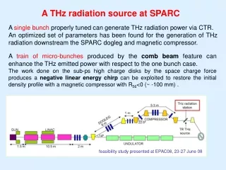
BENCH MEASUREMENTS OF A FAST INTRA-PULSE PHASE-LOCK CONTROL An intra-pulse phase-lock system is under study to actively correct the fast phase jitter coming from the RF stations. Since the RF pulse is about 4.5 ms long, the rise time of such a system should be of the order of 1 ms, corresponding to a bandwidth of about 1 MHz. Consequently a fast phase modulator is needed, while the overall delay of the connections (including the group delay of the RF station) should be limited to 100 ns. The speed of the OpAmps manipulating the signal has also to be adequate.