Enhancements and Developments in the HESR RF System: January 2006 Status Report
This report details the advancements in the HESR RF system as of January 2006. It discusses high-resolution (HR) and high-luminosity (HL) operational modes, including the injection of 200m RESR pulses and innovations in bunch rotation (BR) techniques aimed at reducing energy spread. The stochastic pre-cooling methods utilizing Barrier Bucket systems are highlighted, alongside results from material tests conducted at COSY. Various waveform experiments demonstrate the effectiveness of sinusoidal and rectangular signals in optimizing system performance, paving the way for future designs and applications.

Enhancements and Developments in the HESR RF System: January 2006 Status Report
E N D
Presentation Transcript
RF System for HESR Status report, January 2006 F. Etzkorn / A. Schnase, with help from S. An, K. Bongardt
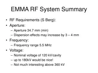
Description of HESR RF System (1) High Resolution (HR) mode: N~1010 Particles • 3 GeV Injection of 200m RESR pulse into HESR Bunch rotation (BR) for reducing energy spread by dual harmonic RF system with (h=1, 2) • Stochastic pre-cooling of DC beam 10% time gap is obtained by Barrier Bucket (h=1,…>5) system • Capture with (h=1, 2); ac-/de-celeration with (h=1) sinusoidal waveform Bunch rotation (BR) for reducing energy spread • Experiments with DC beam, electron/stochastic cooling counteracts target heating 10 % time gap is obtained by Barrier Bucket (h=1,…>5) system • Energy change to 3 GeV: new RESR pulse
Description of HESR RF System (2) High Luminosity (HL) mode:N~1011Particles • 3 GeV Injection of 200m RESR pulse, N<3.5*1010intoHESR Bunch rotation (BR) for reducing energy spread by dual harmonic RF system with (h=1, 2) • Stochastic pre-cooling of DC beam 10 % time gap is obtained by Barrier Bucket, (h=1,…>5) system • Capture & ac-/de-celeration with (h=1, 2) sinusoidal waveform energy spread after pre-cooling is larger for N~1011 Bunch rotation (BR) for reducing energy spread • Experiments with DC beam, electron/stochastic cooling counteracts target heating 10 % time gap is obtained by barrier bucket (h=1,…>5) system • Energy change to 3 GeV: particles are remaining in HESR
Description of HESR RF System (3) • Phase compression of remaining particles to 200m length Bunch rotationby dual harmonic RF system with (h=1, 2) • New RESR pulse is injected into empty half of HESR • Bunch Rotation for new RESR bunch, matching for remaining particles synthetic waveform with (h=1,…5) leads to almost identical energy spread • debunching => DC beam for stochastic pre-cooling : cycle continues Parameter limits for HESR RF system • synthetic waveform, (h=1,…5) : < 3 kV for about 1 sec • Energy change < 200 eV/ turn : (h=1): < 1 kV , (h=2): < 0.3 kV for maximal 300 sec • Barrier Bucket, (h=1,…>5) for storage mode: > 1 V for >3000 sec
Material Tests • At COSY an experiment was performed to study the signal synthesis for Barrier Buckets. • At first, 3 different waveforms of possible Barrier Bucket Signals (Bl = 0.9 / 2µs) were generated and applied to the multi-harmonic COSY Cavity, filled with VitroPerm. • With the results at the gap, the transfer function of the RF system was calculated. • With that transfer function, a pre-distorted function was calculated and applied to the cavity. • The response resulted in exactly that pulse that could be expected with the available bandwidth of the COSY cavity system including the amplifier chain. • A nearly clean pulse shape was obtained
The 3 tested waveforms • Rectangle, sinusoidal and sinusoidal with DC offset • Track 1: Input to amplifier (dark blue) • Track 2: Response at gap (light blue) • sinusoidal with DC offset (proposed by CERN) brings no usable result with our system. rectangle sinusoidal sinusoidal with DC offset
Pre-distorted waveforms Waveforms calculated with 16 harmonics • Track 1: Pre-distorted Input to amplifier • Track 2: Response at gap • Bl=0.9 Period=2µs • Result of rectangle and sinusoidal waveforms are nearly equal • Sinusoidal waveform looks a little better • For nearly rectangular waveform much more harmonics and bandwidth are needed (up to h=50) • We will continue with further tests as soon we have a working prototype system rectangle sinusoidal
Number of harmonics => wave form RF waveform for Bl = 0.8 with different harmonics: voltage ripple leads to islands of stability Fourier decomposition with 5 harmonics
Status of cavity design • It is foreseen to install 2 different sets of cavities. • The first cavity will consist of 2 tanks with an acceleration gap in the centre. It will be driven by a push-pull tube amplifier up to 3kV. It will be broad band to allow multi-harmonic bunch manipulation. It will be used for injection, acceleration and deceleration. Because of the Ripple and noise of the tube amplifier, it’s not useable for small voltages below about 100V. The material will be probably FineMet. • For voltages in the range from 1V to about 100V, a second, single tank cavity, loaded with VitroPerm is foreseen, directly driven by a transistor amplifier. • The tanks will be build inside FZJ similar to the COSY cavity. • A 1 kW transistor amplifier designed by CERN and improved by KEK for J-PARC will be ordered. • An existing tube amplifier of COSY will be modified for broad band use to be able to drive the 2 tank cavity. • Necessary supplies of COSY can be used for the prototype phase.