Download
1 / 30
300 likes | 312 Vues
Learn about the importance of fiber characterization for safeguarding your network investment and ensuring optimal performance. Discover why testing fiber before finalizing network design is crucial.

E N D
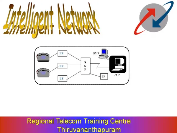
Intelligent Network Investment & Growth Begins With Fiber Characterization Dave Hawkins, Senior Director of Professional Services Jake Sentlingar, Senior Network Architect Fujitsu Network Communications
Agenda • Fiber Characterization OverviewDave Hawkins • What is Fiber Characterization • Why it’s Essential to Test Fiber • Your Network Investment • Technical Overview of Fiber TestingJake Sentlingar • DWDM Network Applications • Impediments to DWDM Transmission • DWDM Network Design
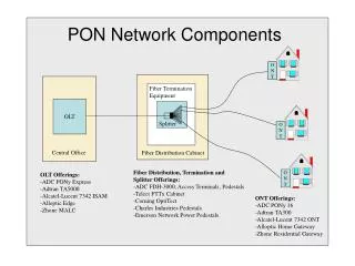
Fiber Characterization What is it? • An essential service to protect your future network investment by letting you know if your embedded fiber will adhere to engineering specifications for critical fiber performance and support the desired network performance Who needs Fiber Characterization? • Anyone considering deployment of a DWDM or high optical carrier (OC) rate network elements When?:Before the final network design and investment AND before moving to a 40 G network What types of tests are conducted? • Optical Time-Domain • Optical Loss • Chromatic Dispersion • Polarization Mode Dispersion Testing is required for any multi-gigabit network to function properly
Anatomy of Fiber Characterization You can only accurately diagnose and prescribe the correct network with testing Tests? NO YES
Why Test Optical Fiber • Impurities, imperfections and other variations can distort and scatter light traveling down a fiber • This will cause power loss and signal disruption • Certain fiber types are problematic even if new • Even if the fiber is originally “perfect”, events occurring during the life of the fiber can cause performance issues: • Splicing • Weather changes – i.e. repeated freezing & thawing • Physical stress – impacts PMD • Micro bends & crushed fibers • Poor connector mating • Dirty fiber or bulk heads
Do it Now or Do it Later… • Test fiber prior to final design: • Guarantee your network performance for 20 years • Create a benchmark for comparison in the event of future issues • Or, you will test later to identify the problem source: • Attempt to fix issues, but it will always be a non-optimized network • You may discover the need for additional equipment • Or you may discover you bought too much or even the wrong equipment • Delays are costly!
Your Long Term Investment.. • Investment in a DWDM network means you plan on future expansion • DWDM supports 40Gb/s or 1.6 Terabits of information • Don’t buy your equipment without testing your fiber • While problems may not be immediately apparent, any growth may require additional capital investment • Example: • You plan to support 32 wavelengths, but your fiber may only work with 16 or fewer • You may now need to double your investment to achieve your intended capacity Why buy DWDM and not care how many wavelengths you can put on it?
Network Investment vs. Fiber Characterization Investment Example of Network Investment: Terminal Basic Node $40K & Up to 40 Transponders @ $25K each Terminal Basic Node $40K & Up to 40 Transponders @ $25K each Test OADM $60K Test OADM $60K Test OADM $60K Test 1 2 3 4 Fiber Characterization investment: 4 spans *~$2500 = $10,000 Network investment At full capacity (40 transponders): $2.26M The cost of testing fiber is less than .5% of network investment!
Potential Investment Impacts When Utilizing Incorrect Data • If you deploy a network using incorrect data, you will spend significantly more than an investment in Fiber Characterization ($10K for 4 spans) • You may also have unnecessary sunk cost in your network • Your project will be delayed resulting in lost revenue • And, your network will always be sub-optimized
Testing “Do”s and “Don’t”s • Do test your fiber to ensure it is capable of supporting DWDM or higher OC applications • Do all testing before finalizing design requirements • If not performed - 90% chance at least one component will need reordering • Do hire a reliable outside source (other than fiber provider) to test fiber • Do establish fiber records for ease in trouble- shooting • Do seek a money back guarantee from network provider—many will offer the guarantee only if you allow them to test the fiber • Do re-shoot fiber if you are growing your network Don’t think your network will not grow! • Today, the standard is 40Gb/s and industry projections predict in 3 years that 100Gb/s will be the standard!
Practical Considerations In Multi-Gigabit DWDM Network Designs Jake SentlingarSenior Network Architect – DWDM December 6, 2006
DWDM Network Applications • Dense Wavelength Division (DWDM) began 20 years ago • Utilizes the installed base of single mode fiber • Various fiber types • Differing DWDM-related (chromatic dispersion) characteristics • Varying conformance to current standards • Plant records subject to relatively large inaccuracies • Good to poor fiber deployment and maintenance practices • Metro, regional and long-haul deployments • Linear, ring and mesh topologies • Protected and unprotected paths per wavelength • NOT a single circuit network – much more complex
DWDM Systems • Multi-wavelength systems • Several to tens of wavelengths per fiber pair • Uni-directional per fiber • Primary operation in the C band (1530 nm to 1565 nm) • Predominantly 100 GHz wavelength spacing • Typically 40 wavelengths • Also operation in the L band (1565 nm to 1625 nm)
DWDM Transmission Rates per Wavelength • Currently 2.5 Gb/s to 10 Gb/s • 40 Gb/s in early 2007 • 100 Gb/s in 2010 • Higher rates as the data market evolves
Basic Impediments to DWDM Transmission • Total span attenuation • Optical Noise • Dispersion • Non-linear effects
Total Span Attenuation • Fiber attenuation in the C band = approximately 0.25 dB/km • Independent of fiber type • Connectors at fiber panels add 0.5 dB per mated pair • Bypass sites • Intra-building connections • Splice loss • Near 0.1 dB per splice for state-of-the-art fusion splicing, • but can be 0.5 dB per splice with older mechanical splicing • Maintenance splices (future fiber cuts) • DWDM equipment • Sum of these = Total span attenuation
Amplifier Selection • Total span attenuation determines the required amplifier type • Low attenuation = low gain amplifier = limited span length • Moderate attenuation = moderate gain amplifier = less limited span • High attenuation = high gain amplifier = least limited span length • Important to use the lowest gain amplifier that is necessary to: • maximize Optical Signal to Noise Ratio (OSNR) • I.e., maximize transponder-to-transponder reach before regeneration is required • minimize capital expense • While insuring that the selected amplifier can also “recognize” the incoming attenuated DWDM composite signal
Optical Noise • Amplifiers contribute noise, reducing the OSNR • Noise contribution is a function of amplifier type and its input level • Cascading amplifiers reduces OSNR logarithmically • Minimum OSNR must be met at the receiver/transponder • To maintain required bit error rate (BER) • Over the twenty year service life • Per-wavelength regeneration is required if the minimum OSNR can not be achieved • Expensive • Avoid if possible • Use the correct amplifier
Impact of the Incorrect Amplifier • Received Composite signal strength is lower than anticipated and lower than the amplifier’s acceptable range • DWDM System fails to operate over that span • Two new amplifiers must be obtained (one at each end of the span) • Received Composite signal strength is higher than anticipated and higher than the amplifier’s acceptable range • Amplifier’s variable attenuators will adjust to proper operating range • System operates but OSNR has been sacrificed • Regeneration may be unnecessarily specified
Basic Dispersion Types • Chromatic • Polarization mode
Chromatic Dispersion • Pulse spreading caused by wavelengths within a pulse traveling at different speeds in the fiber • Pulse widens and flattens • Higher transmission rates can experience “pulse to pulse overlap” • Total dispersion accumulated at each node is dependent on • Span length • Fiber type(s) in the span • Residual dispersion at the previous node • Dispersion magnitude and slope in the C band differ by fiber type
Dispersion by Fiber Type • Graph
Chromatic Dispersion Effects • Does not generally limit transponder-to-transponder reach at 2.5 Gb/s or below • Must be managed at 10Gb/s to maintain the pulse shape within the eye opening of the receiver/transponder • Dispersion compensation modules specific to span fiber type are often required • Important NOT to overcompensate due to potential non-linear effects • Several times more critical to properly manage at 40 Gb/s than at 10 Gb/s • Networks considering future 40Gb/s should insure that chromatic dispersion values are accurate before network design proceeds
Polarization Mode Dispersion (PMD) • Pulse distortion caused by differing transmission speeds in the horizontal and vertical polarizations due to non-circular fiber • Fiber manufactured prior to the mid-1990s did not have an objective or standard for PMD • Excessive PMD has been discovered in proposed DWDM networks and alternate fiber paths were necessary (2 month delay) • Does not limit reach at 2.5 Gb/s or below • Should not exceed about 12 ps/nm-sqrt(km) transponder to transponder at 10 Gb/s • Should not exceed about 4 ps/nm-sqrt(km) transponder to transponder at 40 Gb/s
Nonlinear effects • Energy transfer from one wavelength to another • Caused by interaction of light waves with molecules in the silica medium • Stimulated Brillouin scattering (SBS) • Stimulated Raman scattering (SRS) • Also due to dependence of the refractive index on the intensity of the applied electric field • Self Phase Modulation (SPM) increases the pulse spreading also caused by chromatic dispersion • Cross Phase Modulation (CPM) also increases pulse spreading in a channel due to the variation on the refractive index with intensity on the other channels
Nonlinear effects (cont.) • Limiting launch power into the fiber is necessary to prevent SBS, SRS, SPM and CPM from disabling successful transmission • These effects are negligible at controlled and limited launch power • OR catastrophic at marginally higher launch power - i.e., they are non-linear • Therefore it is not possible to compensate for greater span attenuation than anticipated by increasing the launch power into the fiber • Four Wave Mixing (crosstalk) is the creation of unwanted wavelengths due to mixing of launched wavelengths • Effect can be reduced by insuring a well-controlled and minimal amount of chromatic dispersion
DWDM Network Design • The fiber data provided for each span is assumed by the DWDM network designer to be accurate • Inaccurate data will usually lead to the following: • Delayed deployment • Higher equipment and installation costs • Non-optimized network • Reduced 10 Gb/s reachability • Potentially fewer usable wavelengths • Reduced mesh applications • Difficulty in adding future nodes • Relatively limited 40 Gb/s deployment • Some or all of the above, depending on the particular DWDM network
DWDM Network Design • Accurate span data is a key to a successful, timely and financially optimal DWDM network for initial wavelengths • Accurate span data is necessary to insure that the installed DWDM network provides best possible value over the system life • Additional wavelengths • Higher and higher transmission rates • Mesh networks • Nodes added or removed or reconfigured • Evolving node types