Download
1 / 34
450 likes | 803 Vues
In Situ Monitoring , Measurement and control of Direct Digital Additive Manufacturing. Jyoti Mazumder * University of Michigan January 9th, 2013. * Robert H Lurie Professor of Engineering @ University of Michigan. Outline. Background History of DMD Introduction DMD System Overview

E N D
In Situ Monitoring , Measurement and control of Direct Digital Additive Manufacturing JyotiMazumder* University of Michigan January 9th, 2013 *Robert H Lurie Professor of Engineering @ University of Michigan
Outline Background History of DMD Introduction DMD System Overview Advances in DMD System Geometry Control Temperature Control Composition Prediction Microstructure Prediction Modeling Summary
Running to Moon: Mold & Mirrors 0.5 mm wall thickness in steel Polished to 40 Angstroms!
5 mm Titanium scaffold for implantation study in a mice spinal column * Image Provided by Prof. Scott Hollister Application In Tissue engineering X-Ray of the Ti-Scaffold After Subcutenous Bone GrowthTi~ Bright WhiteBone ~ Blue Grey
Applications in Industry Actual part AEROSPACE REMANUFACTURING DEFENSE RESTORATION OIL & GAS SURFACE PROTECTION AEROSPACE MANUFACTURING MEDICAL FABRICATION AUTOMOTIVE PRODUCT ENHANCEMENT
DARPA SBIR : Spatial Control of Crystal Texture Directional growth of grains from bottom to top of the blade 8
Challenges to achieve the vision • Remote Manufacturing with hot editing • Precision for Near Net shape 3-D components in order of microns • Certify as you build • Approach: In situ monitoring and Closed loop Process control to keep outcome to the desired level
Overview DMD Process Overview • Direct Metal Deposition • High power (any wave length) laser(orEB[needs Vacuum} ,arc) builds parts layer-by-layer out of gas atomized metal powder • 2. DMD Characteristics • 0.005” dimensional accuracy • Fully dense metal • “Controllable” microstructure • Heterogeneous material fabrication capability • Control over internal geometry
How do we certify the product during manufacturing or Remanufacturing by in situ monitoring?
High Power Laser Chiller Work Table Power Supply Unit Control Panel NC CAD/CAM Feed-back Controller DMD System
SOMS Solution Technology • Features: • Real-time • Compact size, light weight • Low price and low operating cost • Benefits • Defect categorization • In-situ monitoring of composition and phase transformation • Improved weld quality • Reduction in cycle time • Reduction of manual inspection • Low scrap cost • Data collection for post processing SMOS Plasma spectrum analysis Heat source (Laser / Arc) Good weld Laser material processing Bead separation Porosity Burn through Weld quality, defect type and cause prediction
Defect Detection and Classification • Support vector machine • Statistical analysis
Pin-hole and Porosity • Pin-hole: Small holes located in the surface of the welded seam • -Difficulty of appearance processing & weakness of joining strength • Spatters: loss of the molten pool because of high velocity of liquid • Key factor: Contour of the spectral intensity (e.g. Zn emission line width)
Closed Loop Geometry Control Camera 1 2 3 Image acquisition cards DMD Processing Center (Logic OR) Over limit Height Controller Figure 8 Cladding Laser beam gating signal [US patent # 6,122,564 and 6,925,346
Temperature Control: Dynamics Input and Output Experimental Setup GPC Temperature Controller Laser powder Pyrometer bead Collecting lens H13 powder flow rate: 10g/min; Scanning speed: 650mm/min; Standoff: 20mm (beam size 2mm) Substrate
Melt Pool Temperature Control • Experimental: • Weight on control: 2×10⁵ • Prediction horizon: 16 • Control horizon: 5 • Tfilter = [1 -0.8] • Simulation: • Weight on control: 100000000 • Prediction horizon: 30 • Control horizon: 5 • Tfilter = [1 -0.8] Red: reference temperature Black: experimental
One Inch Cube Cladding with Temperature Control Molten Pool Temperature Control Cladding A z b a y (a) (b) Substrate 3mm step x (d) (c) Pictures of the deposition at (a) 10th layer, (b) 20th layer, (c) 30th layer and (d) 40th layer Cladding height at different layers
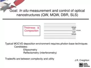
Signal processing unit Laser beam spectrometer bead Collecting lens Substrate Composition Prediction • Alloys without Phase Transformation • Cr-Fe • Ni-Fe • Alloys With Phase Transformation • Ti-Fe • Ni-Al • Ni-Ti Hopper1 Hopper2 Experimental Setup
Composition Prediction: Cr-Fe Alloy • Calibration Curve Line Intensity Plasma Temperature
Prediction of Cr% in the Alloy • Composition Variation < 5%
Ni-Al Alloy Phase Transformation and Line Intensity Ratio (Patent Pending) 10um B2 Ni65Al35 Gamma Prime Ni80Al20 B2 Ni65Al35 Gamma Prime Ni65Al35 ? Ti67.5Fe25.5
XRD Pattern of Ni80Al20 Sample as Deposited (110) (210) (222) (400) (211) (300) (320) (321)
Mathematical Modeling Process modeling of DMD to develop quantitative relationships between parameters for improved process control
Modeling: Governing Equation Continuity equation: Momentum equation: Convection term Diffusion term Darcy term Energy equation: Phase change term at S/L interface Convection term Conduction term Solute equation: Phase diffusion term Phase motion term
Heat transfer / Fluid flowFlow chart & Governing Eqns. • Governing Equations [1, 2] Flux due to relative phase motion Darcy term Buoyancy term
Solute Transport: Advection dominant • Pectlet number C: 3.15x10⁴ Ni:1.69x10⁵ Inside melting pool, Advective transport >> Diffusion transport Nominal composition in 4340 steel:1.75% Ni 0.4% Ni concentration C concentration
Multiple Track Deposition Model Beam size Transition Direction of travel in the second pass Direction of travel in the first pass Scanning length Finish Start Overlap Z Scanning width X The computation domain is not symmetric along laser moving direction Y
Composition and Liquid Velocity Distribution Computed chromium concentration profile: y-z surface x-z surface and x-y surface
Flow Chart 5 4 3 2 1 Thermo-physical Material Properties 6. Initialize / Heat Source Is Phase Detection from Phase Transformation Sensor Same as Calculated One? Is it Rapid Solidification? Yes Heat, Mass And Momentum Calculation Product Stop No Yes 7. Non-Equilibrium Partition Coefficient Change Process Parameter From Calculated Co-relations No Calculate the Composition and Phase
Summary and Conclusion • Process Model • Simulate melt pool temperature, velocity, fluid interface thermal cycle, and composition evolution and distribution • Process Sensor and Control Design, Optimization and Implementation • Geometry Control • Melt pool temperature dynamics and control • Composition sensor • Microstructure sensor • First time in the world one will have the capability to predict the microstructure during the process from plasma, leading to considerable cost and lead time saving
Thank you for your attention! Any questions or comments?