Download
1 / 20
210 likes | 311 Vues
Explore the development and diagnosis process of electrical architecture using Controller Area Network (CAN) and General Motors In-Vehicle Local Area Network (GMLAN). Understand architecture decisions, bus systems, and communication protocols.

E N D
Project 3200 Elektrik – Architektur, Entwicklung – Diagnose Vectra Elektrik – Architektur Entwicklung – Diagnose Vortrag: Oktober 2002 Prof. Dr. Knut Gebhardt Chef Ingenieur Vectra E/E Readiness Adam Opel AG Rüsselsheim
Project 3200 Elektrik – Architektur, Entwicklung – Diagnose • INHALTSVERZEICHNIS • Entwicklungszeitraum • Konzeptauswahl • Bus-orientierte Konzept, incl. Diagnose-Systeme • Entwicklungs-Vortests • End-of-line Test Entwicklung – Durchführung • Service-Tester Entwicklung – Durchführung • Probleme – Lessons learnt
Project 3200 Elektrik – Architektur, Entwicklung – Diagnose Elektrik - Architektur • Konventionell • Bus-orientiert
Project 3200 Elektrik – Architektur, Entwicklung – Diagnose Architektur Entscheidung Kriterien: • Funktionalität • Einbaurestriktionen • Qualitätserwartungen • Servicefreundlichkeit • Kosten
Project 3200 Elektrik – Architektur, Entwicklung – Diagnose Elektrik - Diagnose • Konventionelle Verdrahtung • Beschränkung der Diagnosemöglichkeit • (ohne nennenswerten Zusatzaufwand) • Bussysteme bieten hohe Diagnosetiefe • bei geringem Zusatzaufwand
CAN = Controller Area Network ISO Standard (ISO 11898) Developed by Bosch Widely used in the automotive area Arbitrating (collision avoidance) Max. 8 data bytes per CAN frame Baudrate up to 1MBit/s, variable sample point CAN protocol integrated into hardware (CAN controller) Physical layer depends on application High speed dual wire - up to 1 Mbit/s Fault tolerant dual wire - up to 125 kBit/s Single wire - up to 83,3 kBit/s RS485 ... Project 3200 What is CAN?
Project 3200 What is CAN? • Frame formats • Data frame - Standard format - 11 bit CAN identifier • Data frame - Extended format - 29 bit CAN identifier
GMLAN = General Motors In Vehicle Local Area Newtork Common Architecture for GM vehicles developed in USA and Europe Common communication protocols on all busses Semiconductor industry support of CAN (integrated into C) CAN supports bus speeds high enough to support real time control functions and provides a greater bandwidth Support of wake-up feature to decrease power consumption Project 3200 What is GMLAN?
GMLAN provides a family of serial communication busses to enable ECU’s to communicate with each other. GMLAN comprises of three busses (Low Speed bus, Mid Speed bus, High Speed bus) All of the busses are based on the CAN (Controller Area Network) communications protocol. The use of a given bus in a vehicle depends upon how features/functions in that vehicle are partitioned among different ECU’s. Project 3200 What is GMLAN?
High speed bus (500 kBit/s) Typically used for sharing real time data such as driver commanded torque, actual engine torque, steering angle, etc. Dual wire physical interface (ISO 11898 high speed interface) Max. 16 devices, including the tester OBD/EOBD approved data link (ISO 15765-4) Mid speed bus (95,2 kBit/s) Typically used for infotainment applications (display, navigation, etc.) where the system response time demands that a large amount of data be transmitted in a relatively short amount of time, such as updating a graphics display. Dual wire physical interface (ISO 11898 high speed interface) Max. 16 devices, including the tester Project 3200 GMLAN Communication Busses
Low speed bus (33.3 kBit/s and 83.3 kBit/s) Typically used for operator controlled functions where the system response time requirements are of the order of 100-200 msecs. Single wire physical interface (SAE J2411) Max. 32 devices, including the tester Makes use of the High Voltage Wake Up (HVWU) The High and Mid Sped subnets use a discrete wake up or may wake up on any bus traffic (see next slide) Project 3200 GMLAN Communication Busses - cont’d
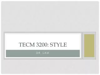
Project 3200 Opel Epsilon J3200 Configuration - cont’d YRS Highspeed-CAN ACC MTA CVT TCM ECM AHL ABS ABS TCS ABS TCS VDC EHPS 6/14 3/11 DLC 12 CIM 1 UEC SDM DSM PAS PDM AHS Singlewire-CAN REC TID Radio IPC SLM DDM BCM K-Line ECC GID CID NHU IHU CAR Phone CDC TU (NHU, IHU) GPS (CAR- PHONE) Midspeed-CAN
Project 3200 Opel Epsilon J3200 Bench Boat
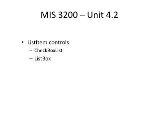
Three Virtual Networks, five physical devices, five Virtual Devices Three independently start-able sets of functionality Unnecessary nodes may be powered down until needed Node containing “switch” activates the Virtual Network on demand Amplifier Backlite Antenna Amp GMLAN CD Tuner Cassette Switch Switch Switch Compact Disk Virtual Network Tuner Virtual Network Cassette Virtual Network Project 3200 Network Management Example #1 • Three Virtual Networks, five physical devices, five Virtual Devices • Three independently start-able sets of functionality • Unnecessary nodes may be powered down until needed • Node containing “switch” activates the Virtual Network on demand
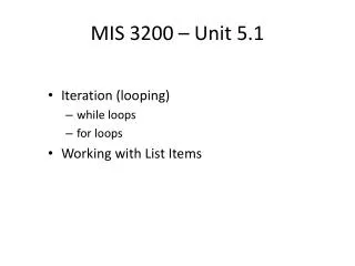
Tree Chart Three Virtual Networks, five physical devices, five Virtual Devices Project 3200 Network Management Example #1 - cont’d
Diagnostic connector pin assignments (16 pin connector) Pin 1: SW-CAN Pin 6: HS-CAN CAN_H Pin 14: HS-CAN CAN_L Pin 3: MS-CAN CAN_H Pin 11: MS-CAN CAN_L Project 3200 GMLAN Communication Busses - cont’d
Project 3200 GMLAN Diagnostics
Functional Based Diagnostic Approach to meet distributed system functionality over multiple ECUs and in-vehicle subnets. Meet diagnostic requirements of in-vehicle Virtual Networks & Virtual Devices. Harmonization of GM J2190 (Class 2) and GM KWP2000 services as "One Global GM Corporate Standard". Project 3200 GMLAN Diagnostics Objectives
Reduction of total number of diagnostic services (test modes) and utilization of minimum amount of CAN Identifiers for Diagnostics. Optimized performance for testing and programming (e.g. Parallel testing/programming of ECUs on multiple subnets). Clear split by concept between Dynamic Real-Time Data Retrieval and Multiple Frame Static Data Messages (non time critical data). Standardized Flash programming procedure Project 3200 GMLAN Diagnostics Objectives - cont’d
Tech 2 Configuration Existing Tech 2 Existing VCI Existing DLC cable New CANdi module Existing DLC Adapters Project 3200 Tech 2 Configuration for CAN Support