Download
1 / 42
420 likes | 614 Vues
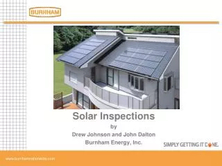
Solar Energy Systems in the Midwest William Guiney Johnson Controls, Inc. Sustainable Design Wednesday, October 5, 2011. Johnson Controls, Inc. Global Headquarters. 385 kW Solar PV Crystalline and Thin Film. 4000 gallon storage tank 34 collectors Solar Thermal. Solar Thermal Project .

E N D
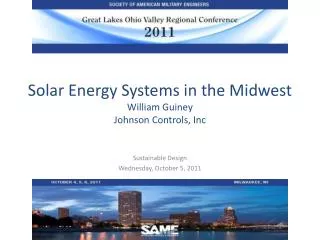
Solar Energy Systems in the MidwestWilliam Guiney Johnson Controls, Inc Sustainable Design Wednesday, October 5, 2011
Johnson Controls, Inc. Global Headquarters 385 kW Solar PV Crystalline and Thin Film 4000 gallon storage tank 34 collectors Solar Thermal
Large Unpressurized Storage Heat Exchanger sized to flow rates Site specific
Drain Back systems • Intermittent loads • Weekday use • Dorms
Glycol systems: • Designed freezing climates • Provide balanced/consistent daily hot water (seven-day loads) • May require heat dump system
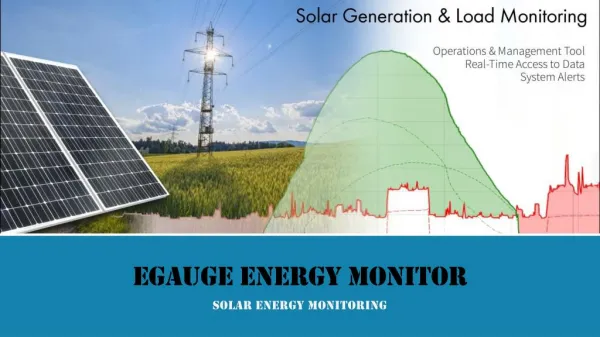
Solar Water Heating Solar Thermal system supplies hot water to the cafeteria, fitness center and lavatories
Expansion Tank and Glycol Make-up Solar Storage and Heat Exchanger BTU Meter Quantifies the Energy Production Solar Circulation Pumps
Hot Water Demand SOLAR THERMAL is DESIGNED for 50-80% of the ACTUAL LOAD
Plug and Play with Pre-Engineered Designs PROPAC ® MASS STORAGE SYSTEMS
Drain Back HTU / Pumping Station Complete Pre-Engineered and Assembled System Kits Eliminate installation errors and maintain factory control
Site Assessment: Introduction • Site assessment is critical for identifying the right location for Solar Thermal systems. • Factors that influence the decision are: • Collector location • Structural limitations • Aesthetics (appearance) • Exposure to elements • Pipe routing • Pipe penetrations • Storage tank size & location (single or multiple tanks)
Site Assessment: Collector Location Rule of Thumb: Keep collector arrays in close proximity to the mechanical room. • Collector arrays may be mounted on: • Roof • Ground • Adjacent building
Site Assessment: Collector Slope • Collector placement should: • Tilt to capture the best average annual performance (latitude) • Winter: latitude plus 10/15 degrees • Summer: latitude minus 10/15 degrees
Site Assessment: Structural Limitations • Key points to consider: • Condition of the roof • Construction details • Wind load zone • Typical additional load to the roof is five to seven pounds
Site Assessment: Exposure to Elements Tip: Walls with parapets are a better choice for mounting (over flat roofs without parapets). • Minimize wind load by: • Installing on interior areas of the roof • Mounting away from roof edges
Site Assessment: Aesthetics Suggestion: Check with area building codes and by laws that may regulate collector location Outward visible appearance to the public eye.
Site Assessment: Identifying the Solar Path Clear solar path will maximize solar production. • Use Solar Pathfinder to identify solar window. • Identify the best solar window for the right system size. • See Solar Thermal portal page for additional information.
RETScreen • Used to estimate system output and % of load • Developed by Canadian Natural Resources Department • Most widely used program of it’s kind worldwide • Free Download - PC only
Rules of Thumb • 1 sq. ft. of flat plate collector will heat 1 to 2 gallons of domestic water per day depending on the climate • Most collectors have similar performance • When comparing collector output, use “Net Aperture” • Smaller is better • Colder the supply temperature - higher the efficiency • Storage may have impact on the performance
PV Overview Solar Photovoltaic
Johnson Controls Global Headquarters5757 Green Bay Avenue Glendale, WI
Different Types of PV Modules Polycrystalline or Multicrystalline Thin Film, Amorphous Single crystal or Monocrystalline U.S. DOE
Basic Grid-Connected PV System Components PV Modules Electric Utility ServiceMeter DC Fusing/Combining System Tie-in Point DC Disconnect AC Disconnect Inverter W Guiney Oct 5, 2011
Determines the actual performance at the customers site. Indianapolis, IN Each 5.25kW block = 6635 kWh/year Atlanta, GA 7235 kWh/yr Miami, FL 7220 kWh/yr Louisville, KY 6635 kWh/yr Milwaukee, WI 6616 kWh/yr Lexington, KY 6460 kWh/yr
PV Site Evaluation Watch out for individual shading obstacles One cell shaded means major power loss.
Rooftop Mounting Systems • Tilt-up rack • Ballasted Rack • Flush-Mount Rack – “Post and Rail”
Photovoltaic System Over a Capped Landfill Bluehole Landfill – Milwaukee, WI 567 kW ballasted PV System
PV Site Evaluation Watch out for inter-row shading on tilt-up arrays
PV Site Evaluation South Module Shadow H Ground Spacing Spacing Required Between Rows for no shading at 9 am (or 3 pm) Dec. 21, at various Latitudes: (This assumes rows are running due east-west) W Guiney Oct 5, 2011
PV Site Evaluation Array Tilt and Orientation Arrays don’t always need to face due south - Annual Power Output for various tilt angles, array directions: Source: NABCEP PV Study Guide
PV Site Evaluation • Choosing location for inverter: • Indoors is usually first choice, but for large inverters this is sometimes not practical • Weight will be an issue • Many inverters have outdoor NEMA 3R enclosures standard • Avoid direct sun locations • Locate inverter near electrical service when possible makes tie-in, and grounding easier Indoor small array inverter Outdoor 250kW inverter
PV Site Evaluation • Locations for combiner boxes, meters & disconnects: • If there is a separate PV meter it may need to be grouped w/building meter • Utility will often require exterior accessible lockable AC disconnect Combiner box and disconnect on the back of the racking System Disconnect and electric utility meter
QUESTIONS ??? Contact Information: