Theremillusion
The Thereminators :. Imen Ben Neticha Snigdha Jonna Sandra Jenkins Steven Bennett Advisor: Professor Siqueira. Theremillusion. Team Members . Imen Ben Neticha EE. Steven Bennett CSE. Snigdha Jonna EE. Sandra Jenkins EE. Responsibilities – Reallocations . Imen

Theremillusion
E N D
Presentation Transcript
The Thereminators: ImenBen Neticha SnigdhaJonna Sandra Jenkins Steven Bennett Advisor: Professor Siqueira Theremillusion
Team Members ImenBen Neticha EE Steven Bennett CSE SnigdhaJonna EE Sandra Jenkins EE
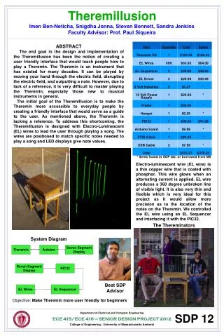
Responsibilities – Reallocations • Imen • EL Wires and EL Sequencer • Visual Output Control • Sandy • Theremin Integration and Troubleshooting • Discrete Mode • Snigdha • Theremin Troubleshooting • Discrete Mode • Steven • Displaying note accuracy programming
Background Invented by Léon Theremin in 1920 Originally got the idea while working on short wave ratio equipment and capacitive sensing during the Civil War in Russia
Motivations for Theremin Modification • No Reference • Continuous Pitch and volume • Need to have extensive ear training
Theremin Principles • Beat Frequency Oscillators
Theremin Kit • Theremax Theremin • Volume and Pitch Antennas • Volume and Pitch field adjustment knobs • Timbre control: useful for external signal processing (aka Discrete Mode) • Manual for general operation and tuning
Discrete Mode-Theremin Analog-to-Digital Converter in a PIC Controller Frequency from the Theremin SWITCH Discrete Signal Processing in MicroController SPEAKERS Voltage to Frequency Converter Digital-to-Analog Converter
Arduino • Consists of a simple microcontroller board, and a development environment for writing software for the board. • This software was utilized to program the Discrete Mode of the Theremin.
Software in Arduino • Frequency measured with peak detection program • The frequency values outputted from the Theremin are grouped together to output a specific frequency based on frequency-to-note conversion.
Conversion table • Pitches.h
PIC32 DSP • 16 Channel 10-Bit ADC • 80 MHz, 1.56 DMIPS/MHz, 32-Bit M4K Core
FFT Demonstration • Configure IO Registers • Allocate and Prepare buffers. • 256 Samples of Analog Signal at 10 KHz • Call Microchip Library Fuction:mips_fft16(dout, calcbuffer, fftc, scratch, log2N) • Meaningful Results: Magnitude/Frequency • Transmit Blocks of Data to USB
What’s Next • Analog Audio can be compared to a Musical Note Lookup Table • Derive a Score fromPlayed Note vs Expected Note
Why the EL Sequencer Easy to use, no need to re-invent the wheel Relatively inexpensive for the amount of hardware (in comparison to building one from scratch) Incorporates programming into the software Using a microwave transformer is more labor, more bulky, and not as accurate (results) Safer. EL wire is 100+V at 4000hz, but very low power. Instead of a shock, you will feel a small tingle if touched in the wrong places
EL Sequencer Board can be powered from USB or LiPo Switch chooses source and acts as on/off Compatible with Arduino (8MHz LilyPad) On-board 8MHz external resonator 8 TRIACs can handle up to 600V Control 8 channels of EL Runs on 3.7V LiPo Footprint for connection to FTDI Basic for downloading code Footprint for connection to Nordic nRF24L01 2.4GHz wireless module ATmega328 based control board that allows the user to program any sequence of blink, on/off, even pulse width modulation (PWM) pulsing of EL wire
TRIACs in the EL Sequencer While EL wire requires very little power, you can't use normal transistors to turn on/off a string of it So we use TRIACs → nifty 'switches' that allow you to turn on/off an AC source Triode for Alternating Current
Integration with PIC32 The EL Sequencer will guide the user with a series of lights. three levels (easy/medium/hard) PIC32 will compare and grade the user PIC32 interfaces with EL sequencer to display score on the EL wires
Theremillusion DEMO Glow Wires
END • Thank You!!!
References • Kenneth D. Skeldon, et al. Physics of the Theremin. Department of Physics and Astronomy, University of Glasgow, Glasgow G12 8QQ, Scotland. Received 15 May 1998; accepted 12 June 1998. • Way, BengKoay; Douglas Beard, Micah Caudle, and Jeffrey Jun-Fey Wong. Theremin. Department of Electrical and Computer Engineering at Mississippi State University. <http://www.ece.msstate.edu/courses/ece4522/projects/2001_spring/theremin/>. • Holloway, Barry. Theremin. Strange Apparatus. 2009-2011. <http://www.strangeapparatus.com/Theremin.html>. • Sparkfun Electronics. “USB 32-bit Whacker – PIC32MX795 Development Board”.<http://www.sparkfun.com/products/9713>. • PAiA, “Theremax FAQ.” <http://www.paia.com/ProdArticles/therefaq.htm>.
Physics of Theremin • Antennas • Difference between Analog/digital theremins • Physics of the variable capacitance and how that changes the oscillators (how oscillators change sound) • Sandy email about finding theremin player
Powering the theremin • Theremin can be powered by 12 volts. • This can be done by building a step-down transformer that will convert the normal house voltage or buy a power cord with a built in converter.
Design Requirements • Visual Display • Will display current note being played and if in teaching mode, indicate how close the note is to target note. • Visual Reference (Fiber Optics) • Lights will indicate the general location the hand has to be in to play a particular note. • (tentative) A light will change color depending on how close or far away the sound is from the target note. • Continuous and Discrete Playing Mode • Device will be able to be switched between playing in the traditional continuous range and playing only discrete notes in specific frequency ranges.
Modular Design Output Processing Frequency to Voltage Voltage to Frequency Voltage Comparison/Discrete Output Pitch Control Mixer/ Detector Switch Visual Interface Optical Fibers Variable Oscillator Display Fixed Oscillator Output control VCA Volume Control Software Interface Variable Oscillator Knob Learning Mode Audio Amplifier Tuning Volume Tuning
FFT Complexity TABLE 1: Representative FFT Operation Counts
Reasons for the Theremin Kit • Building the Theremi • Comparable to creating an acoustic guitar for a woodworker