Download
1 / 34
360 likes | 799 Vues
Usage of OFDM in a wideband fading channel. OFDM signal structure Subcarrier modulation and coding Signals in frequency and time domain Inter-carrier interference Purpose of pilot subcarriers. OFDM example 1: IEEE 802.11a&g (WLAN). Pilot subcarrier. Subcarriers that contain user data.

E N D
Usage of OFDM in a wideband fading channel • OFDM signal structure • Subcarrier modulation and coding • Signals in frequency and time domain • Inter-carrier interference • Purpose of pilot subcarriers
OFDM example 1: IEEE 802.11a&g (WLAN) Pilot subcarrier Subcarriers that contain user data 52 subcarriers Frequency 16.25 MHz 48 data subcarriers + 4 pilot subcarriers. There is a ”null” at the center carrier. Around each data subcarrier is centered a subchannel carrying a low bitrate data signal (low bitrate => no intersymbol interference).
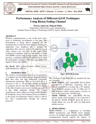
OFDM example 2: IEEE 802.16a (WiMAX) Only 200 of 256 subcarriers are used: 192 data subcarriers + 8 pilot subcarriers. There are 56 ”nulls” (center carrier, 28 lower frequency and 27 higher frequency guard carriers).
Usage of OFDM • OFDM is used in the following systems: • IEEE 802.11a&g (WLAN) • IEEE 802.16a (WiMAX) • ADSL (DMT = Discrete MultiTone) systems • DAB (Digital Audio Broadcasting) • DVB-T (Digital Video Broadcasting) OFDM is spectral efficient, but not power efficient (due to linearity requirements of power amplifier). OFDM is primarily a modulation method; OFDMA is the corresponding multiple access scheme.
OFDM system block diagram Coding & Interl. Bit-to- symbol mapping Modu- lation S/P IFFT Add CP Channel Sync FFT P/S Demod. Deinterl. & Decoding
Subcarrier modulation (IEEE 802.11a&g) BPSK = Binary Phase Shift Keying (PSK) QPSK = Quaternary PSK QAM = Quadrature Amplitude Modulation Modulation BPSK BPSK QPSK QPSK 16-QAM 16-QAM 64-QAM 64-QAM Bit rate 6 Mbit/s 9 Mbit/s 12 Mbit/s 18 Mbit/s 24 Mbit/s 36 Mbit/s 48 Mbit/s 54 Mbit/s Im 16-QAM signal constellation in the complex plane Re
Why (for instance) 54 Mbit/s ? Symbol duration = 4 ms Data-carrying subcarriers = 48 Bits / subchannel = 6 (64-QAM) Bits / OFDM symbol = 6 x 48 = 288 Channel coding: number reduced to 3/4 x 288 = 216 bits/symbol => Bit rate = 216 bits / 4 ms = 54 Mbit/s
Subcarrier modulation and coding N data subcarriers or subchannels carry N data symbols in parallel (= transmitted at the same time). A symbol carries 1 bit (BPSK), 2 bits (4-PSK), 4 bits (16-QAM), or 6 bits of user data (64-QAM). N data symbols in parallel form one OFDM symbol. For each modulation method, there are several coding options for FEC (Forward Error Control). They must be taken into account when calculating user data rates, as shown on the previous slide. Typical coding options: 1/2 (convolutional encoding), 2/3 and 3/4 (puncturing) coding rates.
Gray bit-to-symbol mapping in QAM Gray bit-to-symbol mapping is usually used in QAM systems. The reason: it is optimal in the sense that a symbol error (involving two adjacent symbols in the QAM signal constellation) results in a single bit error. Example for 16-QAM 0010 0110 1110 1010 0011 0111 1111 1011 0001 0101 1101 1001 0000 0100 1100 1000
A rectangular M-ary QAM constellation, where and k is even, is equivalent to two PAM (Pulse Amplitude Modulation) signals on quadrature carriers, each having signal points and symbol error probability . BER performance of QAM (1) Probability of correct symbol decision for M-ary QAM: Proakis, 3rd Ed. 5-2-9 Probability of symbol error for M-ary QAM:
Probability of symbol error for -ary PAM: where is the average SNR per symbol. BER performance of QAM (2) Proakis, 3rd Ed. 5-2-6 Finally, the bit error probability for M-ary QAM: (Gray mapping assumed)
Subcarrier signal in time domain Guard time for preventing intersymbol interference In the receiver, FFT is calculated only over this time period TFFT TG Next symbol Time Symbol duration IEEE 802.11a&g: TG = 0.8 ms, TFFT = 3.2 ms IEEE 802.16a offers flexible bandwidth allocation (i.e. different symbol lengths) and TG choice: TG/TFFT = 1/4, 1/8, 1/16 or 1/32
Orthogonality between subcarriers (1) Orthogonality over this interval Subcarrier n Subcarrier n+1 Previous symbol Guard time Symbol part that is used for FFT calculation at receiver Next symbol
Orthogonality between subcarriers (2) Orthogonality over this interval Subcarrier n Each subcarrier has an integer number of cycles in the FFT calculation interval (in our case 3 and 4 cycles). If this condition is valid, the spectrum of a subchannel contains spectral nulls at all other subcarrier frequencies. Subcarrier n+1 Previous symbol Guard time Symbol part that is used for FFT calculation at receiver Next symbol
Orthogonality between subcarriers (2) Orthogonality over the FFT interval: Phase shift in either subcarrier - orthogonality over the FFT interval is still retained:
Time vs. frequency domain TG TFFT Square-windowed sinusoid in time domain => "sinc" shaped subchannel spectrum in frequency domain
Subchannels in frequency domain Single subchannel OFDM spectrum Subcarrier spacing = 1/TFFT Spectral nulls at other subcarrier frequencies
Presentation of OFDM signal Sequence of OFDM symbols The k:th OFDM symbol (in complex LPE form) is where N = number of subcarriers, T=TG + TFFT= symbol period, and an,k is the complex data symbol modulating the n:th subcarrier during the k:th symbol period.
Multipath effect on subcarrier n (1) Subcarrier n Delayed replicas of subcarrier n Previous symbol Guard time Symbol part that is used for FFT calculation at receiver Next symbol
Multipath effect on subcarrier n (2) Subcarrier n Guard time not exceeded: Delayed multipath replicas do not affect the orthogonality behavior of the subcarrier in frequency domain. There are still spectral nulls at other subcarrier frequencies. Delayed replicas of subcarrier n Previous symbol Guard time Symbol part that is used for FFT calculation at receiver Next symbol
Multipath effect on subcarrier n (3) Subcarrier n Mathematical explanation: Sum of sinusoids (with the same frequency but with different magnitudes and phases) = still a pure sinusoid with the same frequency (and with resultant magnitude and phase). Delayed replicas of subcarrier n Previous symbol Guard time Symbol part that is used for FFT calculation at receiver Next symbol
Multipath effect on subcarrier n (4) Subcarrier n Replicas with large delay Previous symbol Guard time Symbol part that is used for FFT calculation at receiver Next symbol
Multipath effect on subcarrier n (5) Subcarrier n Guard time exceeded: Delayed multipath replicas affect the orthogonality behavior of the subchannels in frequency domain. There are no more spectral nulls at other subcarrier frequencies => this causes inter-carrier interference. Replicas with large delay Previous symbol Guard time Symbol part that is used for FFT calculation at receiver Next symbol
Multipath effect on subcarrier n (6) Subcarrier n Mathematical explanation: Strongly delayed multipath replicas are no longer pure sinusoids! Replicas with large delay Previous symbol Guard time Symbol part that is used for FFT calculation at receiver Next symbol
Task of pilot subcarriers Pilot subcarriers contain signal values that are known in the receiver. These pilot signals are used in the receiver for correcting the magnitude (important in QAM) and phase shift offsets of the received symbols (see signal constellation example on the right). Im Received symbol Re Transmitted symbol
Transmitted and received subcarrier n Transmitted subcarrier n Phase error Received subcarrier n Magnitude error Previous symbol Guard time Symbol part that is used for FFT calculation at receiver Next symbol
Frequency offset at receiver Frequency offset causes inter-carrier interference (ICI) Magnitude Frequency Frequency offset
Summary: Inter-carrier interference Inter-carrier interference (ICI) means that the orthogonality between different subchannels in the OFDM signal is destroyed. There are two causes of inter-carrier interference: Delay spread of radio channel exceeds guard interval Frequency offset at the receiver
Pilot allocation example 1 (1) To be able to equalize the frequency response of a frequency selective channel, pilot subcarriers must be inserted at certain frequencies: Pilot subcarriers Time Between pilot subcarriers, some form of interpolation is necessary! Frequency Subcarrier of an OFDM symbol
Pilot allocation example 1 (2) The Shannon sampling theorem must be satisfied, otherwise error-free interpolation is not possible: maximum delay spread Time Frequency
Pilot allocation example 2 (1) An alternative pilot scheme for equalizing the frequency response of a frequency selective channel: Between pilot symbols, some form of interpolation is necessary! Time Pilot OFDM symbols Frequency Subcarrier of an OFDM symbol
Pilot allocation example 2 (2) The Shannon sampling theorem must again be satisfied, otherwise error-free interpolation is not possible: maximum p-p Doppler spread maximum Doppler frequency Time Frequency
Pilot allocation example 3 An efficient pilot scheme (used in DVB-T) makes use of interpolation both in frequency and time domain: Interpolation necessary both in frequency and time domain! Time Black circles = Pilot subcarriers Frequency
Summary: OFDM features In summary, OFDM offers the following features: Multipath propagation (fading) does not cause intersymbol or intercarrier interference if the guard interval is sufficiently large and there is no frequency offset at the receiver. Multipath fading, however, causes frequency selectivity in the transmission bandwidth. Pilot signals are employed for correcting (equalizing) the magnitude and phase of the received subcarriers at the pilot subcarrier frequencies. Some form of interpolation is necessary for equalization at other than pilot subcarrier frequencies. Many pilot allocation schemes have been proposed in the literature, see e.g. www.s3.kth.se/signal/grad/OFDM/URSIOFDM9808.htm