Download
1 / 32
320 likes | 505 Vues
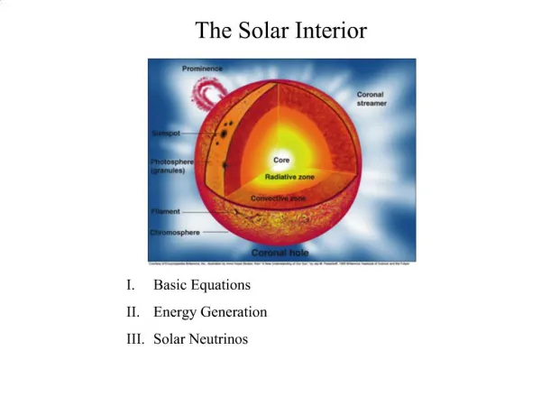
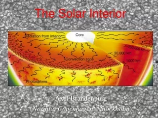
Understanding Links Between the Solar Interior and Atmosphere. Brian Welsch, George Fisher*, and Bill Abbett Space Sciences Laboratory, UC Berkeley. *NB : much material presented here was borrowed from George!. Links between the interior and atmosphere?!.

E N D
Understanding Links Between the Solar Interior and Atmosphere Brian Welsch, George Fisher*, and Bill Abbett Space Sciences Laboratory, UC Berkeley *NB: much material presented here was borrowed from George!
Links between the interior and atmosphere?! Are you kidding?? There are too many! And CMEs! And flares! Coronal heating! Well, not driving them. Waves, current sheets, however --- it’s all from the convection! But at least their ultimate source. And maybe a trigger. Oh, yeah, and solar wind acceleration! Links, links, everywhere… an interior conspiracy! And streamer structure, and corotating interaction regions! What about the grassy knoll?! Call in Glenn Beck!
The Usual Idea: The Interior Drives the Atmosphere • Primarily a tale of magnetic energy transport. • Heterodoxy: The Atmosphere Can Drive the Interior! • On short and long time scales, and in steady state. Restricted Focus!
Magnetic energy --- from the interior! --- drives flares and CMEs, as well as coronal heating. From T.G. Forbes, “A Review on the Genesis of Coronal Mass Ejections”, JGR (2000)
Magnetic energy must get from the interior into the atmosphere, implying an outward energy flux. • The Poynting flux of magnetic energydepends upon E, or in the ideal MHD approx., -(v x B)/c: dU/dt = ∫ dASz= c ∫dA (E x B)z /4π= ∫dA (B x[vx B])z /4π • Hence, photospheric electric fields --- or flows, if the flux is frozen-in --- play a central role in the solar activity that interests most of us!
Digression: a thought experiment emphasizes the role of convective driving in atmospheric evolution. Q: What would happen if all photosphericflows ceased? (For this exercise, ignore the fact that the Sun needs these flows to expel the heat it produces!) Partial answers, I believe: • The corona would relax, on the Alfvén time – fast! – but would then do basically nothing! • Coronal heating would cease – no driver! • Flares wouldn’t happen – no new energy/perturbations! • Fast CMEs wouldn’t occur -- but perhaps some streamer blowouts, via slow magnetic reconnection
The PTD method can also be used to decompose the magnetic field, and determine E from its evolution. ^ ^ ^ ^ tB = x (xtBz) +xtJztBz= h2(tB) 4πtJz/c= h2(tJ) h·(tBh) = h2(z(tB)) B = x ( xB z) +xJz Bz = -h2B, 4πJz/c= h2J, h·Bh= h2(zB) Left: the full vector field B in AR 8210. Right: the part of Bh due only to Jz.
Faraday’s law,B/t = -c( x E) = x (v x B), can then be used -- but this does not fully determine E! Note that: tBh also depends upon vertical derivativesin Eh, which single-heightmagnetograms do not fully constrain. But most importantly: Faraday’s law only relates tB to the curl of E, not E itself; a “gauge electric field” ψis unconstrained by tB. ==> Even multiple-height magnetograms won’t fix this! Ohm’s law is one additional constraint. What about others?
Important magnetodynamics is not always apparent in ΔBz/Δt -- e.g., flux emergence! Schematic illustration of flux emergence in a bipolar magnetic region, viewed in cross-section normal to the polarity inversion line (PIL). But Doppler measurements can detect vertical flows along PILs! Note the strong signature of the field change at the edges of the region, while the field change at the PIL is zero.
Aside: Flows v|| along B do not contribute to E = -(vxB)/c, but do “contaminate” Doppler measurements. Generally, Doppler shifts cannot distinguish flows parallel to B (red), perpendicularto B(green), or in an intermediate direction (blue). With v estimated another way & projected onto the LOS, the Doppler shift determines v|| (Georgoulis & LaBonte2006). Doppler shifts are only unambiguous along polarity inversion lines (PILs), where Bn changes sign (Chaeet al. 2004, Lites 2005). vLOS v v = vLOS v vLOS
How can Doppler shifts be combined with the inductive electric field EIfrom PTD? • NearPILsof BLOS, Doppler shifts and Btransverse unambiguously determine a“Doppler electric field:” • We define the PIL-weighted “modulated” field EM, • We can then find the curl-free component of EM, via
Next, we combine Eχ and the PTD EI field, and then find another potential field to ensure total E is ideal. The total electric field is given by where we used the iterative scheme of Fisher et al. (2010) to determine the scalar potential ψ, so that E⋅B=0, as implied by the ideal Ohm’s law, E = -(v x B)/c.
Validation is essential before use with real data! Use MHD simulation with known magnetic field evolution, electric fields, and velocity fields: Our test case is an ANMHD simulation of a bipolar magnetic region rising through a convecting medium. The simulation was performed by Bill Abbett. Welsch et al. (ApJ 2007) used this same simulation for a detailed evaluation and comparison of velocity/electric-field inversion techniques.
How accurate are our methods? We tested them with MHD simulations of emerging flux from Welsch et al. (2007). Top row: The three components of the electric field E and the vertical Poyntingflux Sz from the MHD reference simulation of emerging magnetic flux in a turbulent convection zone. 2nd row: The inductive components of E and Szdetermined using the PTD method. 3rd row: E and Szderived by incorporating Doppler flows around PILs into the PTD solutions. Note the dramatic improvement in the estimate of Sz. See Fisher et al., Sol. Phys, in press, and http://arxiv.org/abs/1101.4086
Qualitative and quantitative comparisons show good recovery of the simulation’s E-field and Poynting flux Sz. Left: A comparison of the vertical component of the Poynting flux derived from the PTD method alone with the actual Poynting flux of the MHD reference simulation. Right: A comparison between the simulated results and the improved technique that incorporates information about the vertical flow field around PILs into the PTD solutions. Poyntingflux units are in [105 G2 km s−1] See Fisher et al., Sol. Phys, in press, and http://arxiv.org/abs/1101.4086
The Usual Idea: The Interior Drives the Atmosphere • Primarily a tale of magnetic energy transport. • Heterodoxy: The Atmosphere Can Drive the Interior! • On short and long time scales, and in steady state. Restricted Focus!
The Usual Idea: The Interior Drives the Atmosphere • Primarily a tale of magnetic energy transport. • Heterodoxy: The Atmosphere Can Drive the Interior! • On short and long time scales, and in steady state. Restricted Focus!
On short time scales: Lorentz forces during flares might cause sunquakes! Hudson (2000): coronal fields should “implode” in flares and CMEs. Wang & Liu (2010) report that photospheric fields often become “more horizontal” during flares. A sudden field change can produce a Lorentz “jerk” on the interior: See Fisher et al., Sol. Phys., in revision, http://arxiv.org/abs/1006.5247 • Kosovichev & Zharkova, 1998
In steady state: Quiet-sun surface layers are regions of divergingPoynting flux! • Poynting Flux At the surface, strong downflows in strong-field concentrations (turbulent pumping!) imply a downward Poynting flux. Abbett & Fisher “find a… positive… Poynting flux… along the edges of overturning granules above the surface where the field is being compressed.” The surface is a special place: flows do work on the magnetic field! Steiner et al. (2008) refer to the visible surface as “a separatrix for the vertically-directed Poynting Flux” • Abbett & Fisher (2011) See Abbett & Fisher, Sol. Phys., in press, http://arxiv.org/abs/1102.1035
Long-term: What process removes all the flux from active regions over a solar cycle? Every solar cycle, ~3000 ARs emerge, each with ~1022Mx of unsigned flux. And every cycle it must be removed from the photosphere ---somehow! • Babcock (1961)
HMI’s measurements of Doppler shifts & transverse fields along PILs can constrain flux removal. • Low (2001) • Spruit et al. (1987) Which model more accurately describes the Sun? • Van Ballegooijen (2008) Several models of cancellation have been proposed, including emergence of U-loops, and submergence of Ω loops. • Kubo et al. (2010)
But there’s a problem with using HMIdata for this technique: the convective blueshift! Because rising plasma is (1) brighter (it’s hotter), and (2) occupies more area, there’s an intensity-blueshift correlation (talk to P. Scherrer!) S. Couvidat: line center for HMI is derived from the median of Doppler velocities in the central 90% of the solar disk --- hence, this bias is present! Punchline: HMI Doppler shifts are not absolutely calibrated! (Helioseismology uses time evolution of Doppler shifts, doesn’t need calibration.) Line “bisector” From Dravins et al. (1981)
Because magnetic fields suppress convection, there are pseudo-redshifts in magnetized regions, as on these PILs. Here, an automated method (Welsch & Li 2008) identified PILs in a subregion of AR 11117, color-coded by Doppler shift.
The pseudo-redshift bias is evident in scatter plots of Doppler shift vs. |BLOS |. • I find pseudo-redshifts of ~0.15 m/s/G. • Schuck (2010) reported a similar trend in MDI data.
Ideally, the change in LOS flux ΔΦLOS/Δt should equal twice the flux change ΔΦPIL/Δtfromvertical flows transporting Bhacross the PIL (black dashed line). ΔΦPIL/Δt ΔΦLOS/Δt • NB: The analysis here applies only near disk center!
We can use this constraint to calibrate the bias in the velocity zero point, v0, in observed Doppler shifts! Abias velocity v0 implies := “magnetic length” of PIL • ButΔΦLOS/2 should match ΔΦPIL, so we can solve for v0: (Eqn. 3) NB: v0 should be the SAME for ALLPILs==> solve statistically!
In sample HMI Data, wesolved for v0using dozens of PILs from several successive magnetograms in AR 11117. • v0 ± σ = 266 ± 46 m/s Error bars on v0 were computed assuming uncertainties of ±20 G on BLOS, ±70G on Btrs, and ±20 m/s on vDopp. • v0 ± σ = 320 ± 44 m/s • v0 ± σ = 293 ± 41 m/s
The inferred offset velocity v0 can be used to correct Doppler shifts along PILs.
How do bias velocities vary in time, and with parameter choices? - The two main paramsare PIL “dilation” d and threshold |BLOS|. • - black: d=5, |BLOS|= 60G; red: d=3, |BLOS|= 60G; blue: d=5, |BLOS|= 100G The radial component of SDO’s orbital velocity (dashed line) varies on a similar time scale.
The values we find for the convective blueshiftagree with expectations from line bisector studies. Asplund & Collet (2003) used radiative MHD simulations to investigate bisectors in Fe I lines similar to HMI’s 6173 Å line, and found convective blueshifts of a few hundred m/s. From Gray (2009): Solar lines formed deeper in the atmosphere, where convective upflows are present, are blue-shifted. Dots indicate the lowest point on the bisectors.
Aside: Doppler velocities probably can’t be calibrated by fitting the center-to-limb variation. Snodgrass (1984), Hathaway (1992, 2002), and Schuck (2010) fitted center-to-limb Doppler velocities. But such fits only yield the difference in Doppler shift between the center and the limb; they don’t fit any “DC” bias! • Toward the limb, horizontal components of granular flows contribute to Doppler shifts. • But the shape and optical thickness of granules imply receding flows will be obscured. • Hence, it’s likely that there’s also a blueshifttoward the limb!
Summary • The Interior Can Drive Evolution In the Atmosphere! • Duh, we knew that… • But by estimating the photosphericPoynting flux, we can try to quantify this driving! • Processes in the Atmosphere Can Affect the Interior! • Changes in magnetic fields above the photosphere can cause a Lorentz jerk on the interior --- perhaps causing sunquakes. • Generic properties of convection do work on magnetic fields at the surface, and lead to a Poynting-flux divergence in the Quiet Sun. • Doppler shifts along PILs --- properly calibrated! --- can constrain how much active region flux cancels by submergence, and by emergence.