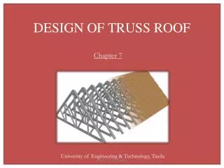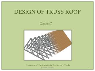
Roof Truss Setout
380 likes | 1.29k Vues
Process Overview. Roof truss setout is about correctly applying truss technology to roof shapes in the building design. The process is as follows:Use roof lines on the drawings to convert roof shapes into discrete truss areas known as

Roof Truss Setout
E N D
Presentation Transcript
1. Roof Truss Setout
2. Process Overview Roof truss setout is about correctly applying truss technology to roof shapes in the building design. The process is as follows:
Use roof lines on the drawings to convert roof shapes into discrete truss areas known as �blocks�
Set the positions of key trusses in each block
Set the positions of remaining trusses
Determine where valley infills are required (at joins in truss blocks)
3. Reading Roof Shapes From Drawings For newcomers to roof design it is a good idea to learn how to read roof designs in terms of lines on a drawing. Some may already have this skill, if not, click here to learn about how to Read Roof shapes from drawings
4. Converting Roof Shapes into Truss Blocks Truss set out begins by breaking the roof shape up into individual truss blocks. Roof lines read from the drawing assist this process:
Use ridge lines to help identify individual blocks
Identify spans for each block using ridge lines and support wall locations
Define block lengths using ridge lengths plus roof ends e.g. gables, hips, Dutch gables
The steps are repeated over and over until each block is defined - , start with the widest block then gradually work towards the smallest
To demonstrate, a simple roof shape will be used to provide a worked example
5. Ridge lines determine the span and the direction of the trusses
The number of ridges usually determines the number of different truss blocks in the overall roof area (i.e. 2 ridges = 2 blocks)
Start by selecting the most central ridge in the plan and/or the highest ridge when viewed in perspective or elevation. This usually identifies the block with the widest span Use Ridge Lines to Identify Individual Blocks
6. Defining Block Span Define the span of the widest block using the ridge line in conjunction with �Pitching lines�
Pitching lines are defined by the heel points of trusses. The distance in between the points represents the span (as taken from the outside of the support walls). To help find the heel points:
Look at the roof in cross section - work down the ridge along the underside of the top chords until intersecting with the underside of the bottom chord i.e. the heel point
The heel point is also usually at the outer edge of the support walls - an exception is where cantilevered trusses are involved
Be careful to differentiate the support parts of the wall from other parts e.g. don�t include the brick veneer.
7. Once the span has been determined, translate it to lines on either side of the block (in this case, on either side of ridge line A). These lines are referred to as �Pitching lines�
8. Defining Block Length The ridge length plus roof end types define the block length
End types include treatments such as Gables ends, Dutch gable ends and Hip ends, that occur at the end of the ridge line (but exclude overhangs)
9. Completing the Process - Defining Secondary Truss Blocks Having completed Block A, other areas must be dealt with such as Block B. These are secondary areas and if more than one, should be dealt with in order of span - largest to smallest
10. Closing Openings at Interfaces Between Blocks At the interface between truss blocks � such as the interface between Blocks A and B - the situation occurs where there are no support walls to carry trusses spanning Block A
To make up for the missing wall, a standard girder truss must be placed across the missing link to support trusses spanning Block A
12. Locating Key Trusses For Different End Types Having located standard girder trusses necessary to close of truss blocks, the next step is to locate key trusses associated with each end type, including:
Gable ends
Hip ends
Dutch gable ends
Each type has a key truss with a fixed location that determines the setout of other trusses in and around the end
13. Setting Out Gable Ends Gable end trusses are positioned either above or immediately next to the inside of end walls
Surrounding trusses are setout relative to the chosen point (i.e. standard trusses are spaced inwards towards the centre of the block, overhang trusses or verge framework are spaced outwards)
14. The choice between locating the Gable end truss �on� or �next to� the end wall, depends on structural considerations. For instances Gable end trusses may be
fully supported by the end wall or
free spanning between the side walls but next to the end wall (shown in blue)
A separate presentation is available for greater detail on gable and eaves construction
15. Setting Out Hip Ends The hip end is built around the Truncated Girder truss which transfers the weight of the hipped roof section to the side walls.
16. Truncated Girder added and Dutch Gable Girder added.Truncated Girder added and Dutch Gable Girder added.
17. After locating the Truncated Girder, hip trusses (shown in blue) are placed along the hip lines
The top chords of these trusses pass over the Truncated Girder finishing at the apex.
To assist this, the first Standard truss may be placed across the apex to help stabilise the ends of the Hip trusses (it is shown behind the Truncated Girder in green)
18. Jack trusses are added across the mid section of the hip end (shown in brown)
Again, the top chord of these trusses passes over the Truncated Girder
They butt into the Hip trusses or the apex (if using a centred Jack truss) and graduate in length as they progress up the hip
19. Creeper trusses are spaced between the Jack, Hip and Truncated Girder trusses (as shown with brackets below)
These trusses butt into the Hip truss and graduate in size as they progress up the hip
Unlike jack trusses, these trusses relate to the lower end of the hips and therefore the top chord does not extend over the Truncated Girder
20. The Standard Truncated truss (shown in blue) occurs higher up the hip - between the Truncated Girder and the first Standard Truss
It doesn�t carry extra loads like the Truncated Girder truss, it simply acts as a regularly spaced trusses but with the top cut-off to suit the roof shape
22. Hips are sometimes setout using alternative framing methods to the method just shown. These methods still use the truncated trusses, but hip, jack and creeper trusses may be replaced by conventional rafters and ceiling joists. Two approaches to this are shown (as follows) Alternative Hip End Setout
23. The method below is notable for the way the Truncated Girder carries the loads of the ceiling joists, creeper rafters and hip rafters:
The ceiling joists (shown brown) run into the bottom chord of the Truncated Girder truss
The hip rafters (shown blue) run over the Truncated Girder and up to the apex
The creeper rafters (shown brown) run into the hip rafters
24. The alternative method (below):
Still makes use of the Truncated Girder to carry the ceiling joists, creeper rafters and hip rafters
Differs from the previous method in running the ceiling joists parallel to the bottom chord of the truncated girder truss
It uses Hanger beams (shown in blue) to provide intermediate support for the ceiling joists - the beams are supported by the bottom chord of the Truncated Girder truss
25. Setting Out Dutch Hips/Gables Dutch Hips are also called Dutch gables and are built around a special truss called a Dutch Hip Girder
It must contend with the fact that Dutch hip is in conceptual terms, half hip and half gable. The Girder forms the interface between the two.
It has a waling plate fixed to one side of the truss which provides support for the hip end trusses. The upper part forms the face of the gable
26. Truncated Girder added and Dutch Gable Girder added.Truncated Girder added and Dutch Gable Girder added.
30. Standard trusses added. Note no overhang where they are carried by Primary Girder.Standard trusses added. Note no overhang where they are carried by Primary Girder.
31. Setting Out Trusses Between Ends Having located Gable, Hip, and Dutch Hip ends, standard trusses for each block fit in between (in this example the standard trusses are shown in blue, for Block A). The trusses may be spaced:
From one end until reaching the the closing space at the other end
From both ends until reaching the closing space in the middle
In either case, the spacing must not exceed the nominated maximum spacing e.g. 600mm
32. Though the term �standard� implies all trusses of this type are the same, they still vary slightly where things like overhangs or cantilevers create specific needs
Check the layout to identify where minor variations in standard trusses may arise. For instance the blue trusses shown below, don�t have overhangs where they butt into the girder truss (shown in green). They therefore differ slightly compared to the Standard trusses on either side
33. Standard trusses added. Note no overhang where they are carried by Primary Girder.Standard trusses added. Note no overhang where they are carried by Primary Girder.
34. Joining Blocks With Valley Ends Valley ends are used when connecting two perpendicular truss blocks together � as is the case in joining Blocks A and B together. The valleys are actually made using saddle trusses (shown in blue) to make the connection. They join the roof planes of the two blocks thus forming a ridge line and valley lines.
36. Making Sure You�ve Chosen the Best Truss Setout Special attention and review of truss design is required where:
Complex nests of roof shapes are involved � thus creating complex interfaces between truss blocks
Roofs aren�t based on rectangular wall layouts � thus making truss blocks hard to define
Truss blocks with abnormal proportions of span versus length
Truss blocks that join in odd or tenuous ways
Truss blocks with different pitching heights on either side of the span
37. In the previous situations, multiple setout options may present themselves. The following criteria provide some tips for identifying the best option:
Keep the cost of truss production down by keeping girder trusses to the smallest span possible
Keep wide and open ceiling spans to a minimum � internal walls that break up the spans reduce the visual impact of large cambers in long span trusses
Minimise the effect of heavy girder trusses on the wall framing below e.g. avoid girder trusses sitting on lintels and other wall beams
38. Click on the arrow below to end, or an option below