Download
1 / 43
430 likes | 588 Vues
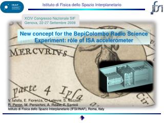
The ISA accelerometer role in the Radio Science Experiments of the BepiColombo mission to Mercury. V. Iafolla, D.M. Lucchesi, S. Nozzoli, F. Santoli, R. Peron , E. Fiorenza, C. Lefevre, A. Reale. Istituto di Fisica dello Spazio Interplanetario (IFSI/INAF), Roma, Italy.

E N D
The ISA accelerometer role in the Radio Science Experiments of the BepiColombo mission to Mercury V. Iafolla, D.M. Lucchesi, S. Nozzoli, F. Santoli, R. Peron, E. Fiorenza, C. Lefevre, A. Reale Istituto di Fisica dello Spazio Interplanetario (IFSI/INAF), Roma, Italy X Congresso Nazionale di Scienze Planetarie Bormio, 17-21 Gennaio 2011
The BepiColombo Radio Science Experiments The space mission BepiColombo (BC), one of the Cornerstones of the European Space Agency (ESA), aims to perform (Grard & Balogh, 2001; Iess & Boscagli 2001; Milani et al., 2001, 2002): a detailed study of the planet Mercury and its environment and to test Einstein’s General Relativity (GR) to an unprecedented level of accuracy Launch window opens on 21 July 2014, start of science February 2021: 1 year of nominal duration + 1 year of extended mission Launch on Ariane 5 ECA
The BepiColombo Radio Science Experiments The accurate knowledge of the Mercury Planetary Orbiter (MPO) orbit represents the way to achieve a large part of these targets: • The MPO will be characterized by a polar orbit around Mercury, with a semi–major axis of about 3389 km and a relatively high eccentricity of 0.162 • The MPO will be a 3–axis stabilized spacecraft, Nadir pointing, and equipped with a complete set of instruments in order to perform Radio Science Experiments (RSE) • 400x1500 polar orbit (red trajectory) • The Mercury Magnetospheric Orbiter (MMO) orbit is optimized for studying the interaction of the planet’s magnetic field with solar wind and Sun’s magnetic field • It is a 400x12,000 km polar orbit (yellow trajectory)
The BepiColombo Radio Science Experiments The RSE, represents a complex mix of measurements and scientific objectives and, very interesting, it is not possible to separate them neatly in independent experiments. However, we can distinguish: a gravimetryexperiment a rotation experiment a relativity experiment • Basically, on–board the MPO, the instruments used for these experiments are: • Ka–band Transponder • Star–Tracker • High Resolution Camera • Accelerometer 1. Tracking: L. Iess (Univ. Rome) PI – MORE 2. Accelerometer: V. Iafolla (IFSI/INAF Rome) PI – ISA 3. High Resolution Camera: E. Flamini (ASI Rome) PI – SYMBIOSYS 4. Orbit determination: A. Milani (Univ. Pisa) - MORE
The BepiColombo Radio Science Experiments The scientific goals to achieve by means of very precise measurements are: the global gravity field of Mercury and its temporal variations due to solar tides (in order to constrain the internal structure of the planet) the local gravity anomalies (in order to constrain the mantle structure of the planet and the interface between mantle and crust) the rotation state of Mercury (in order to constrain the size and the physical state of the core of the planet) the orbit of Mercury’scenter–of–mass (CoM) around the Sun and the propagation of electromagnetic waves (in order to improve the determination of the parameterized post–newtonian (PPN) parameters of GR)
The BepiColombo Radio Science Experiments These kinds of measurements are based on: rangeand range–rate derivations of the MPO position with respect to Earth–bound radar station(s) (and then of Mercury’sCoM around the Sun) the determination of the non–gravitationalsignals on the MPO by means of an on–board Accelerometer the determination of the MPOabsolute attitude by means of a Star–Tracker the determination of angular displacements of referencepoints on the solid surface of the planet by means of an High Resolution Camera
The BepiColombo Radio Science Experiments The BepiColombo RSE and tracking performance The very ambitious goals of the BepiColombo RSE require a strong synergy among the following main aspects: • Accurate tracking from Earth ground station(s) • Non–gravitational perturbations measurements • Precise Orbit Determination (POD) As proved by the numerical simulations (Milani et al., 2001, 2002), the ranging accuracy needs to be significantly more accurate than presently is. The requirements for the tracking system are (Iess and Boscagli, 2001): Range: 20 – 30 cm (2-way) Range rate: 3104 cm/s (2-way) The integration times for the range-rate (Doppler) are between 1000 s and 10,000 s, while the frequency stability is about 11014 at 1000 s integration times.
Mercury The BepiColombo Radio Science Experiments Precise orbit determination We need an accuracy in the along-track orbit reconstruction of about 1 m over one orbital revolution of the MPO around Mercury, i.e., over 8355 s. The requested accuracy corresponds to an along-track acceleration of about 108 m/s2. This quantity has been assumed equal to ISA measurement error over the arc length during the POD
The Italian Spring Accelerometer measurements • The Italian Spring Accelerometer (ISA) (Iafolla & Nozzoli, 2001) is a three-axis harmonic oscillator that has been selected by ESA to fly on-board the MPO • The main target of ISA is to measure the complex and subtle non–gravitational accelerations (NGA) in the strong radiation environment of Mercury, which is characterized by strong day/night asymmetries and a huge variation of the solar irradiance during the sidereal year • The NGA are proportional to the area-to-mass ratio of the body, and are very difficult to be properly modelled for a complex in shape and active satellite like the MPO (Lucchesi & Iafolla, 2006) • Indeed, the modelling depends on a set of parameters related with the physical properties of the satellite surface and structure, which will be strongly influenced, and with unknown laws, by the strong radiation environment in the surroundings of Mercury • ISA allows to remove the NGA from the equations of motion in such a way to reconstruct the pure gravitational orbit of a reference point of the MPO spacecraft • This will be of fundamental importance to guarantee the very ambitious objectives of the BepiColombo mission to Mercury
The Italian Spring Accelerometer measurements • Non–gravitational accelerations (NGA), our main target for the RSE • Accelerations due to gravity gradients • Apparent accelerations • MPO center-of-mass (CM) accelerations • Accelerations due to thruster maneuvres In formula, this translates in: which imposes requirement and knowledge in the position of the test masses and in the attitude of the spacecraft, as well as in the spacecraft CM drifts and accelerations.
proof–mass Pick–up capacitors Control capacitors Proof–mass flexural foil The Italian Spring Accelerometer measurements ISAbehaves like a linear harmonic oscillator but it is a flexural oscillator presently obtained by working a single piece of aluminium 5056. The pick-up system of the accelerometer is based on capacitors read–out: Thales Alenia Space (Milano, Italy) is the industrial contractor in charge of the built and test of the space version of ISA accelerometer.
Temperature variations: Mercury half sidereal period (44 days) 25°C peak-to-peak MPO orbital period (2.325 h) 4°C peak-to-peak Random noise 10°C /Hz The Italian Spring Accelerometer measurements ISA main physical characteristics and thermal constraints ISA thermal stability: Sensor thermal sensitivity 5107 m/s2/°C Electronic thermal sensitivity 1108 m/s2/°C Active thermal control attenuation 700 ISA oscillator parameters: Mass 200 g Resonance frequency 3.9 Hz Mechanical quality factor 10 ISA performance: Measurement band–width 3105– 1101Hz Intrinsic noise 1109 m/s2/Hz Measurement accuracy 1108 m/s2 Dynamics 300108 m/s2 A/D converter saturation 3000108 m/s2 Iafolla et al., 2004; Iafolla et al., 2006; Iafolla et al., 2007
HGA ISA CM Mercury ISA position inside the MPO ISA new position Presently, following a suggestion of ASD (H.R. Schulte) the RSE measurements will not be referred to the spacecraft CM or the theHGA phase center, but to the accelerometer reference point. This as a result of the difficulties in determining the MPO CM with the needed accuracy. The equations of motion are very simple in this case. Indeed, the main purpose of the precise orbit determination (POD) is to fix a point for which we can easily write the equations of motion in such a way that they contain the dynamic parameters to which we are interested to. Usually, this point is the spacecraft CM: spacecraft CM acceleration where U represents the gravitational potential at the spacecraft CM.
ISA position inside the MPO ISA new position (*) which represents the spacecraft CM acceleration as a function of the accelerometer measurements, and it is a complex to solve equation. If we refer to the accelerometer, we obtain: (**) for the inertial acceleration, and: for the equation of motion of the accelerometer. (***)
ISA position inside the MPO ISA new position (*) which represents the spacecraft CM acceleration as a function of the accelerometer measurements, and it is a complex to solve equation. If we refer to the accelerometer, we obtain: (**) for the inertial acceleration, and: for the equation of motion of the accelerometer. (***) This equation is simpler than (*) because of the cancellation of the apparent accelerations and those related with the CM drifts.
ISA position inside the MPO ISA new position Practically, we do not need to remove any signal from the accelerometer readings, nor to constrain any effect in its measurements, as for the case of the previous position of ISA. All the measurements are “true” accelerations that we must transfer to the MORE team in order to allow them to perform the very precise orbit determination of the BepiColomboRSE. Obviously, we have three proof–masses. This implies that we need to refer three reference points (the three CM of ISA proof–masses) to just one single point of the accelerometer box inside the MPO. Moreover, also the HGA phase center has to be referred to this reference point of the accelerometer, with about a 2 mm knowledge.
Calibrationon ground Measurement of rotation matrix between ISA axes and optical cube Measurement of transduction factors for ISA sensing elements Check of alignment constancy after vibrational tests Measurement of sensing masses position at zero gravity Check of alignment constancy in time and possible measurement of aging Check of alignment constancy after thermal stress
Axesdirectionscalibration • Goal: to measure the direction of each sensing axis with respect to IDA UOAF • Measurement principle and setup architecture already addressed
Axesdirectionscalibration Experimental activities performed to validate general measurement idea and to evaluate main error sources
Calibrationin cruise Trajectory with launch on 19 July2014 ESA, BC-ESC-RP-05500, Issue 3.2
Calibrationin cruise Required information for in-cruise calibration • Estimation of tracking accuracy during SCE, and therefore of the accuracy in recovering the MCS acceleration • Estimation of the expected acceleration signal acting on the MCS, to be confronted with the tracking accuracy and accelerometer sensitivity • Re-assessment of expected signals acting on the sensing elements, taking into account the different positioning of ISA with respect to MCS COM (instead of MPO COM) Transducer factor
Calibrationin cruise • Periodical checkouts • Long-term stability tests • Zero position of the sensing masses: potential drifts in the working positions of the sensing masses will be detectable by a continuous read-out • Noise level: the solar radiation pressure and the residual vibrations on MCS being the only source of vibration noise, it will be possible to test the instrument intrinsic noise with high accuracy
Calibrationin orbit • Nominal procedure: calibration using the internal actuators before every measurement arc • Backup procedure: calibration using the external acceleration produced by dedicated MPO manoeuvres every TBD days and every time the calibration with internal actuators shows an anomalous change of ISA parameters To be taken into account • The allowed manoeuvres, both in type and temporal allocation (this will require close co-operation with ESOC) • The MPO COM knowledge, still an important factor for this type of calibration (TBC) • ISA measurement band and sensitivity: the calibration signal must be inside ISA band and should be inside its dynamics
Reaction wheels discharge and thrusters firing The onboard reaction wheels (RW) are primary used for attitude control, in particular to guarantee the nadir pointing of the MPO spacecraft during its nominal mission around Mercury The MPO has four (small mass) RW arranged in a tetrahedral configuration: BC–ASD–TN–00051
Reaction wheels discharge and thrusters firing • The small mass of the RW has a less impact on the onboard micro–vibration noise, but requires a desaturationmanoeuvre (DSM) for the discharging of the accumulated momentum every 12h, with respect to the 24h originally planned • These DSM will be performed during unobserved arcs from Earth ground station(s) and will typically span over 9 minutes (540 s) • However, because of the RSE requirements, in particular from the rotation experiment, the nadir pointing is still mandatory during these manoeuvres • Hence the onboard thrusters will be used to still guarantee the nadir pointing • Therefore, two of these DSM had to be planned during each unobserved arc
BOT EOT BOT unobserved arc T=8h 10h 22h 8h 24h Oh T=12h tracking DSM2 DSM1 Reaction wheels discharge and thrusters firing A typical (possible) schedule of the events related with the DSM: BOT = Beginning Of Tracking EOT = End Of Tracking • The speed variations DeltaV imparted by the thrusters will change the MPO orbit and will dramatically impact, if not known properly, on the estimate of the spacecraft state–vector (position and velocity) at the beginning of the subsequent tracking arc • THIS will have a quite negative impact on the accuracy of the mission RSE
Reaction wheels discharge and thrusters firing The MPO is equipped with two complementary set of thrusters: • the 22 N set • the 10 N set • the 22 N set is composed of 2x4 thrusters acting along the –Z-axis, they are used for DeltaVrealization • the 10 N set is composed of 2x4 thrusters acting in the X=0 plane at 30° of the +Y-axis; they are used for 3-axis torque capability for AOCS control • the +Z-axis is along the radial direction and nadir pointing (yaw-axis) • the +X-axis is in the orbital plane along the transversal direction (roll-axis) • the +Y-axis is perpendicular to the other two (pitch-axis) From ASTRIUM specifications, the thrusters misalignment could be up to 2°, with a pointing adjustment of about ± 3° (half cone aperture)
Reaction wheels discharge and thrusters firing High temperature HGA Finned radiator for protection from planet.Multiple radiator segments for specific temperature needs Radiation Monitor Sensors Star Trackers LGA 10 N attitude control thrusters X High temperature MLI LGA Y Apertures from structure and umbilical separation closed by Deployable Thermal Covers Z Instrument aperture 22 N orbit control thrusters
Reaction wheels discharge and thrusters firing From ASTRIUM (Hans Schulte, TN of 17-04-09) we had the following information about the performances of the thrusters: • Nominal force: 10 N between (7.8 – 9.1) N in operational conditions • Pulse duration: 0.1 s • Pulse repetition rate: 9.0 s • Total linear momentum: 40 Ns nominally in across-track direction • De-saturation manoeuvre: 540 s (9 min) t0 = 0.1 s with a 1.1% duty cycle T = 9 s
MORE requirements (DeltaPDR 27/28-11-2008) Reaction wheels discharge and thrusters firing • Because of the MPO RSE requirements it is important to assess if the discharging manoeuvres are able to degradate the MPO orbit reconstruction, i.e., the satellite state vector accuracy at the beginning of the subsequent tracked arc • The spacecraft along-track position shall be known with an accuracy of about 10 m at the beginning of each tracking arc, and (possibly) not exceeding 15 m at subsequent epochs • This translates in an along-track acceleration accuracy of about 2108 m/s2 over the tracking session The linear speed variations to be measured (V) and their knowledge ((V)) are: X (transversal) Z (radial) Y(across-track) V: 0.00 mm/s 17.00 mm/s 42.00 mm/s (V): 0.15 mm/s 0.80 mm/s 2.10 mm/s
ISA as a tool for V measurements • In 2009 during an ISA/MORE progress meeting in Roma, V.I. suggested to use ISA measurements during the DSM of the spacecraft RW in order to measure the speed variations DeltaV imparted by the on board thrusters • This possibility, if accepted by the scientific team, will be very attractive under several points, in primisby both the industrial contractor and ESA, because with no additional mass impact on the spacecraft • The main requirement needed by ISA team in order to perform the measurements, is in terms, as we shall see, of the maximum acceleration to be measured • In other words, we must avoid the saturation of the accelerometer during the measurements
The V impact on the orbit reconstruction • Simulations performed on the DeltaVimpact on the MPO orbit show that the misalignment of the spacecraft thrusters may significantly impact in the accuracy of the along-track position knowledge: 16 m accuracy against 10 m • This tells us that the on ground characterization of the thrusters represents a very important issue to be carefully considered by the MORE team • Obviously, our analysis has been very conservative in the estimate of the residual displacement in the along-track position • Indeed, we have considered the sum of the absolute values of the residuals of the various effects. Hence, the 16.2 m estimate that we obtained may be considered as an upper bound for the along-track displacement knowledge
ISA accuracy ISA as a tool for V measurements Because we are mainly interested in the along-track accuracy, the main speed variation to be considered over the time span of the DSM, about 540 s, is that in the radial direction: Vz 17 mm/s. t0 = 0.1 s Therefore, ISA seems to be able to measure the estimated accelerations, as averaged values over the de-saturation manoeuvre, with an accuracy of about 108m/s2 T = 9 s XZY V (mm/s) 2 17 42 <a> (m/s2) 3.70106 3.15105 7.78105 <a>/A0 370 3.15103 7.78103 1·D 10·D 26·D Needed dynamics
ISA accuracy ISA as a tool for V measurements From the mechanical point of view there are no problem with the accelerometer dynamics and saturation. Indeed, the proof-masses are about 50 m distant from the capacitor plates. The minimum acceleration capable to produce the proof-mass hit is: 0.6 m 11.6 m 4.7 m XZY V (mm/s) 2 17.1 42 <a> (m/s2) 3.70106 3.17105 7.78105 <a>/A0 370 3.17103 7.78103 1·D 10·D 26·D Needed dynamics
ISA as a tool for V measurements • As we can see from the last row of the Table, the accelerations to be measured are roughly 1 times, 10 times and 26 times ISA dynamics, i.e., the maximum allowed acceleration to be measured during the nominal operations of ISA, i.e., during the tracking session • However, this is not a real problem. Indeed, the dynamics of 300·10−9gis the one necessary to guarantee a measurement accuracy of 1·10−9g during an orbital arc of about 8 h in order to fulfill the RSE objectives • By varying the gain of the accelerometer we can increase the dynamics (when necessary) at the expense of ISA accuracy • Therefore, the maximum precision of our measurement is at the level of 1/300, that is 0.3% • For accelerations larger than the actual dynamics, the precision of the measurements remain ≈ 1/300, but with an accuracy lower than the nominal value of 1·10−9g • The main requirement is in the out–of–plane direction, because the acceleration to be measured is 2.6 times the saturation level of ISA
Average value to be measured ISA as a tool for V measurements ISA simulations Practically, from the accelerometer measurements we must be able to reproduce the input acceleration profile, and its frequency content, for each of the three proof–masses of ISA accelerometer More precisely, in the time domain, from the accelerometer measurements we must be able to “read” the average acceleration over the time span of the DSM Lets focus on the radial acceleration:
ISA oscillator parameters: Mass m = 200 g Resonance frequency f0 = 3.9 Hz Mechanical quality factor Q = 10 ISA as a tool for V measurements ISA simulations: time domain results We simulated ISA as a second order linear system forced by a rectangular shaped acceleration train: Effective average value to be reconstructed ISA accuracy ISA dynamics
ISA as a tool for V measurements ISA simulations: time domain results Results for the radial displacement Z(t) and the reconstructed radial acceleration az(t): Without filtering the high frequencies 2.8% discrepancy with respect to az 2.7% discrepancy with respect to az
ISA as a tool for V measurements ISA simulations: time domain results Results after filtering the high frequency with a Chebyshev 2nd-order low pass filter: ISA dynamics For different configurations of the Chebyshev filter the results have been in the range of : 0.1%–0.8% Cut-off: 6·10–3 Hz Ripple: 0.01 dB peak-to-peak 0.6% discrepancy with respect to az 0.6% discrepancy with respect to az
envelope ISA as a tool for V measurements ISA simulations: frequency domain results • The aim of the Fourier analysis is to expand a general function as a trigonometric series under well defined conditions from the mathematical point of view • The amplitude of each line of the spectra, i.e., each Fourier coefficient, contains a bit of the information of the original signal in the time domain, and it is a rapidly decreasing function, in general, of the order nof the Fourier series expansion • Therefore, it is not easy, in general, to estimate the coefficient of order n = 0 from the Fourier coefficients with order n 0 • In the case of a rectangular train of pulses, the coefficient of order zero, i.e., the constant term of the Fourier expansion, is equal to the average amplitude of the train over a single cycle and also over the entire time sequence: t0 = 0.1 s T = 9 s Fourier expansion, with T > t0 n = 0 n 1 natural, and = n0
Accelerometer bandwidth: 3105– 1101Hz ISA as a tool for V measurements ISA simulations: frequency domain results • As we can from the equation, the amplitude of each Fourier coefficient, starting from a1 at the fundamental frequency of 0.1 Hz (i.e., 1/T), is very close to a0, at least for the first coefficients. • In particular, the difference between a1 and a0 is less than 0.02%! • Indeed: for nsmall; • Moreover, the spectral line relative to this coefficient is very close to the upper bound of the accelerometer bandwidth, and there will be not additional requirements for its measure with regard to the environment noise of the MPO spacecraft. Therefore, in the frequency domain, our goal translates in the determination of the coefficient a1. • The relation between the input acceleration and the accelerometer response is ( = frequency): • Therefore, by computing the FFT Z() of the accelerometer response Z(t), and using ISA Transfer Function H(), we obtain:
ISA as a tool for V measurements ISA simulations: frequency domain results The figure shows the results of the computation: In order to obtain such a result we have low–pass filtered the accelerometer output displacement with a Chebyshev filter of the 3th–order, with a cut–off frequency at 0.9 Hz and a 1 dB peak–to–peak ripple in the filter pass–band. The same result may be obtained by directly computing the FFT of the acceleration reconstructed from the accelerometer measurements. These results, obtained in the frequency domain, are superior with respect to those obtained in the time domain. In particular the filtering procedure is less cumbersome, and very good results have been also obtained without the application of the filter. The present result corresponds to a final reconstructed velocity of 17.12 mm/s, practically coincident with that produced by the original (input) acceleration signal.
Conclusions • ISA accelerometer is an important part of the BepiColombo RSE aimed at establishing important results on Mercury geophysics and fundamental physics • A new concept for the RSE has been suggested for this mission, referring the measurements to the accelerometer reference point and thereby avoiding the problems connected with MPO center of mass knowledge • Calibration procedures in all the phases of the mission are essential to fully employ the instrument characteristics • A further advantage of having an accelerometer onboard is the possibility of directly measuring the reaction wheels discharging manoeuvres, thereby boosting POD