
Uploaded by
corine
10 SLIDES
273 VUES
100LIKES
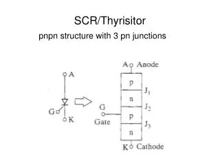
SCR/Thyrisitor
DESCRIPTION
SCR/Thyrisitor. pnpn structure with 3 pn junctions. Cross-section of the pnpn structure. + V AK -. J1. J2. J3. I A = 0.
Download
1 / 10
Télécharger la présentation 
SCR/Thyrisitor
An Image/Link below is provided (as is) to download presentation
Download Policy: Content on the Website is provided to you AS IS for your information and personal use and may not be sold / licensed / shared on other websites without getting consent from its author.
Content is provided to you AS IS for your information and personal use only.
Download presentation by click this link.
While downloading, if for some reason you are not able to download a presentation, the publisher may have deleted the file from their server.
During download, if you can't get a presentation, the file might be deleted by the publisher.
E N D
Presentation Transcript
SCR/Thyrisitor pnpn structure with 3 pn junctions
Cross-section of the pnpn structure + VAK - J1 J2 J3 IA = 0 Apply a forward bias voltage to the Anode-Cathode Junctions J1 and J3 are forward biased Junction J2 is reverse biased Only a small amount of current flows from A to K The device is in it’s OFF or “Forward Blocking” State
SCR/Thyristor (continued) + VAK - IA Increase the Anode-Cathode voltage until “breakdown” occurs. Anode current increases. “Conducting state”
More Related