Emitter Follower: Class A Output Stage Basics
Understand the operation of a Class A output stage using an emitter follower circuit. Learn about conduction angle, biasing techniques, voltage gain, current gain, and circuit analysis. Explore resistor and current mirror biasing methods. Optimize power dissipation and maximize output swing for efficient performance. Use Microcap simulation for practical application.

Emitter Follower: Class A Output Stage Basics
E N D
Presentation Transcript
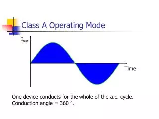
Class A Operating Mode Iout Time One device conducts for the whole of the a.c. cycle. Conduction angle = 360 °.
Class A Output Stage • Transistors only conduct current in one direction. • 360° conduction angle therefore requires a d.c. bias so that the collector current does not try to go negative. • Common circuit design is the Emitter Follower or Common Collector Amplifier.
Emitter Follower Basics • As long as the collector current is positive, VBE» 0.7 V. • VE, therefore equals VB – 0.7 V, i.e. unity voltage gain. • Input current will be approximately b times smaller than output current though – i.e. current gain.
Emitter Follower Analysis Quiescent Conditions
A.C. Response To relate vout to vin, must relate base voltage, vb to vin and vout to vb. vb
(I) – vout vs. vb vb ve
iRB iIN iB (II) - vin vs. vb Potential divider is formed between RS and rin.
Bias Current Two possible ways of approximating the 15 mA current source : Resistor Current Mirror
Resistor Biasing When the output voltage is at its lowest possible value, the output transistor has just turned off : i.e. maximum output signal has 7.5 V peak amplitude
Current Mirror Biasing Again, when the output transistor has just turned off :
Resistor vs. Current Mirror • Resistor biasing is simpler and cheaper than building a current mirror, however… • Maximum output swing is limited using a resistor. • The extra resistor appears in parallel with RL, thereby lowering rin. • Power dissipation is increased.
Microcap simulation #1 EEM3A-1.CIR
Summary • A class A output stage can be realised by an emitter follower circuit. • Voltage gain is approximately unity. • Current gain is high. • Ideally, a current mirror is required to bias the emitter follower.