ECET 350 Topic 2 Complete DeVry
ECET 350 Topic 2 Complete DeVry<br>Just Click on Below Link To Download This Course:<br>https://www.coursetutor.us/product/ecet-350-topic-2-complete-devry/<br>ECET 350 Topic 2 Complete DeVry<br>ECET 350 Topic 2 Discussion<br>WEEK 2: NYQUIST SAMPLING REQUIREMENTS<br>You are given an input signal with a maximum input frequency of 1 kHz. Also, given that the Nyquist criteria <br>

ECET 350 Topic 2 Complete DeVry
E N D
Presentation Transcript
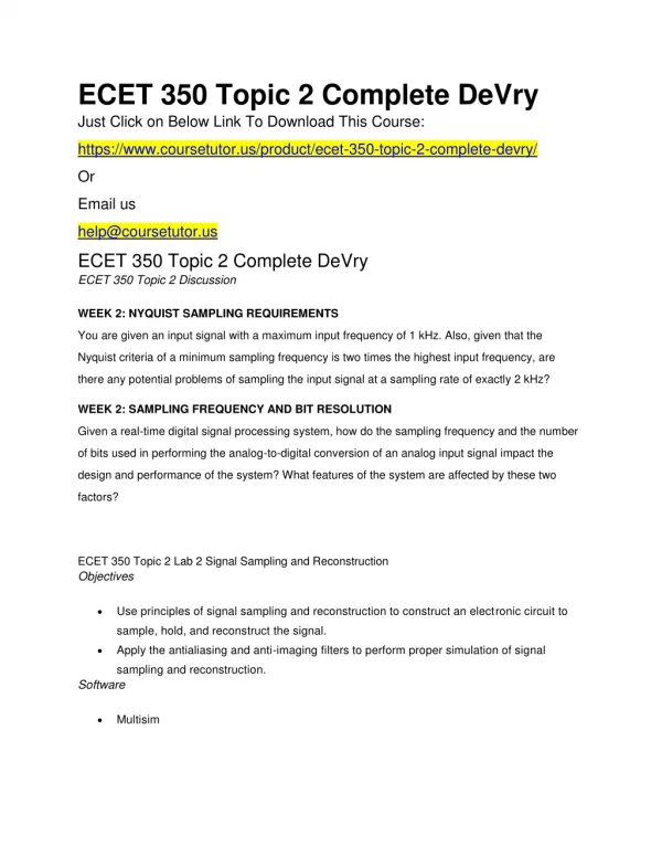
ECET 350 Topic 2 Complete DeVry Just Click on Below Link To Download This Course: https://www.coursetutor.us/product/ecet-350-topic-2-complete-devry/ Or Email us help@coursetutor.us ECET 350 Topic 2 Complete DeVry ECET 350 Topic 2 Discussion WEEK 2: NYQUIST SAMPLING REQUIREMENTS You are given an input signal with a maximum input frequency of 1 kHz. Also, given that the Nyquist criteria of a minimum sampling frequency is two times the highest input frequency, are there any potential problems of sampling the input signal at a sampling rate of exactly 2 kHz? WEEK 2: SAMPLING FREQUENCY AND BIT RESOLUTION Given a real-time digital signal processing system, how do the sampling frequency and the number of bits used in performing the analog-to-digital conversion of an analog input signal impact the design and performance of the system? What features of the system are affected by these two factors? ECET 350 Topic 2 Lab 2 Signal Sampling and Reconstruction Objectives Use principles of signal sampling and reconstruction to construct an electronic circuit to sample, hold, and reconstruct the signal. Apply the antialiasing and anti-imaging filters to perform proper simulation of signal sampling and reconstruction. Software Multisim
Introduction Signal sampling is usually performed by sampling an analog signal at appropriate rates according to the Nyquist theorem and then holding the sampled voltage during the time required for the ADC to convert the voltage level to a binary code (digital value). The analog signal should be band- limited so that the sampling frequency can be chosen according to the Nyquist theorem, namely , in which is the maximum frequency or the upper band of the analog signal. To ensure that the signal is band-limited, an antialiasing filter (restricting low-pass filter) is deployed as the first block in the path of the input signal. The digital value, the output of ADC, could be processed using a DSP algorithm mainly composed of a digital filter. After digitally processing the signal, it has to be reconstructed and delivered back to the analog world, which is the binary code, and the result of DSP operation is converted back to a sample and hold voltage level. The converted voltage levels are further fed to the anti-image filter (smoothing low-pass filter) to reconstruct the analog signal. Figure 1A shows the complete signal sampling and reconstruction system. To investigate signal sampling and reconstruction in this lab experiment, a simplified system that omits the DSP section is shown in Figure 1B. Figures 1A and 1B: Signal Sampling and Reconstruction If the sampling condition is violated, the aliasing would occur. This effect will cause undesired frequencies known as alias frequencies within the information frequency band.
To avoid aliasing, Figure 2A shows the sampling and reconstruction using an antialiasing filter. Figure 2B shows the simplified system that omits the DSP section and will be used in this lab experiment for simulation. Figures 2A and 2B: Signal Sampling and Reconstruction With an Antialiasing Filter Deliverables Answer all questions, complete all tables, and paste all figures and graphs in the Week 2 Lab Cover Sheet here (Links to an external site.) . Submit your Week 2 Lab assignment. You can also download the cover sheet for Week 2 Lab in the Files section of the Course Menu. Required Software Multisim Access the software at https://lab.devry.edu (Links to an external site.). All Steps Lab Steps STEP 1: Antialiasing and Anti-imaging Filter Specifications Using MultiSim, construct the circuit shown as Figure 3. Set the sampling rectangular pulses (sampling clock) as the following. Vp (pulse value) = -5 volts Period: 0.125 ms
Pulse width 0.02 ms Set the sinusoidal voltage source as the following. Frequency = 1000 Hz Vp (amplitude)=1 volts=0.707 rms, DC offset = 1 volt Explanation of the circuit: Two opamps on the top are the buffer amplifiers before and after the sampler. Sampler is a JFET used as analog switch; its gate is driven by the narrow pulse train as specified above. There are two identical active low-pass filters used for antialiasing and anti- imaging with second order, Sallen-Key topology. Before simulation, address the following questions and include your answers in the Lab cover report. 1. Determine the cutoff frequency of the antialiasing and anti-imaging active filters used in the circuit. 2. Frequency of the signal to be sampled 3. Sampling period 4. Sampling frequency 5. Is the sampling theorem satisfied? Justify your answer. 6. Predict the frequencies and estimated voltage amplitude of each frequency in the range from 0 Hz to 10 kHz of the sampled signals according to the sampling theorem.
Figure 3: Sampling and Reconstruction Circuit As Built in MultiSim STEP 2: Antialiasing and Anti-imaging Filter Simulation Open the first spectrum analyzer by left double clicking on the icon. In the frequency section, set start to 0 Hz and end to 10 kHz. Then click on Enter. Set the amplitude range to 0.25 V/Div and Lin(Linear) display. Set the frequency resolution to 100 Hz. Start the simulation by clicking on the power switch in the top right hand corner of the window. Copy the screen display on the spectrum analyzer to include in your report, use Alt+Print Scrn buttons to capture the spectrum analyzer view only when it is selected, and paste it in your Lab cover report in the section marked antialiasing and anti-imaging spectrum analyzer screen capture.
Using the mouse, move the cursor so that it overlays the center of the spectral signal on the simulator. Use the cursor to measure the frequency and RMS voltage for each peak from 0 to 10 kHz, and record your measurements in Table 1 in your Lab cover report. STEP 3: Signal Reconstruction Simulation The original signal can be fully recovered by low-pass filtering (anti-image filtering) the sampled signal if the sampling condition is satisfied. Left double click on the second spectrum analyzer attached to the low-pass filter. Run the simulation using the same setting of the spectrum analyzer. Copy the screen display on the spectrum analyzer to include in your Lab cover report in the space provided, and label the graph. Use the spectrum analyzer to answer the questions at the end of the lab. Include your answers in the Week 2 Lab cover report in the space provided. STEP 4: Antialiasing Simulation Now disconnect the input sinusoidal source from the antialiasing filter, and connect it directly to the buffer preceding the sampler (see Figure 4). Set the sinusoidal function as the following. Frequency = 7000 Hz Vp (amplitude) =1 volts=0.707 rms, DC offset = 1 volt
Figure 4: Sampling and Reconstruction Circuit While Skipping Antialiasing Filter Left double click on the first spectrum analyzer attached to the second buffer amplifier before the anti-imaging filter. Run the simulation using the same setting of the spectrum analyzer. Copy the screen display on the spectrum analyzer to include in your Lab cover report. Label the graph. The original signal cannot be fully recovered by anti-image filtering the sampled signal if the sampling condition is not satisfied. Left double click on the second spectrum analyzer attached to the anti-imaging filter. Run the simulation using the same setting of the spectrum analyzer.
Copy the screen display on the spectrum analyzer to include in your Lab cover report. Label the graph. STEP 5: Signal Reconstruction Simulation Now, use the same setting for the sinusoidal function as the following. Frequency = 7000 Hz Vp (amplitude) =1 volts=0.707 rms, DC offset = 1 volt Connect the sinusoidal function output to the input of the antialiasing filter as in Figure 3. Run the simulation using the same setting for both of the spectrum analyzers. Copy the screen display on the spectrum analyzer 2 on the output of the anti-imaging filter to include in your Week 2 Lab cover report and paste it in the space provided. Graded Questions From the first spectrum analyzer captured in Step 3: 1. What is the expected frequency after signal reconstruction? 2. What is the frequency measured from the spectrum? 3. Did you fully recover the original signal? From the first spectrum analyzer captured in Step 4: 4. Frequency of the signal to be sampled 5. Sampling frequency 6. Is the sampling theorem satisfied? 7. List frequencies of the sampled signals in the range from 0 to 10 kHz. From the second spectrum analyzer captured in Step 4: 8. Did you fully recover the original signal? 9. List the aliasing frequencies, if any. From the spectrum analyzer captured in Step 5: 10. Frequency of the signal to be sampled 11. Sampling frequency
12. Is the sampling theorem satisfied? 13. Can you find frequencies of the sampled signals for the range from 0 to 10 kHz? ECET 350 Topic 2 HOMEWORK Chapter 2, pages 49 – 56, problems 2a, 2b, 5, 6, 8, 14, 16, 28 Don’t forget to submit your assignment. ECET 350 Topic 2 COURSE PROJECT PRELIMINARY PROJECT DESIGN & PARTS ORDERING The teams must start to research the design and find a low power op amp. Don’t forget to order parts that are needed for the design. See the Course Project Overview in Introduction and Resources. Nothing is to be submitted this week. Download File Now