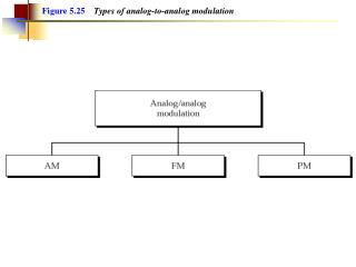
Analog Modulation
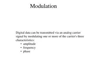
Analog Modulation. AM(Amplitude Modulation) Demodulation of AM Signals Angle Modulation. Why modulate ?. Ease of radiation The size of antenna /4 = c/4f

Analog Modulation
E N D
Presentation Transcript
Analog Modulation AM(Amplitude Modulation) Demodulation of AM Signals Angle Modulation
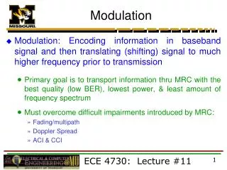
Why modulate ? • Ease of radiation • The size of antenna /4 = c/4f • If we wish to throw a piece of paper(baseband signal), it cannot go too far by itself. But by wrapping it around a stone(carrier), it can be thrown over a longer distance • Simultaneous transmission of several signals • FDM(Frequency Division Modulation) • Reduce the influence of interference • Frequency Hopping • Effecting the exchange of SNR with B • Shannon’s equation : • C is rate of information change per second (bit/s)
Modulated Signal Message Signal (or modulating Signal) Modulator Properties of analog modulation • Time domain representation of the modulated signal • Frequency domain representation of the modulated signal • Bandwidth of the modulated signal • Power component of the modulated signal • SNR after demodulation
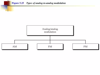
AM (Amplitude modulation) • Also known as “Linear modulation) • Small bandwidth, Power inefficient • Applications • AM radio, TV video broadcasting(VSB), Point-to-point communications(SSB), Transmission of many telephone channels over microwave links • Class of AM • DSB-AM(Double Side Band – AM) • BW = 2W = 2 * BW of the message signal • SSB-AM(Single Side Band – AM) • BW = W • VSB-AM(Vestigial Side Band – AM) • BW = W ~ 2W
DSB – AM • Amplitude of modulated signal is proportional to the message signal
U(f) DSB-AM M(f) 2W A AAc2/2 f f -W 0 W -fc fc DSB-AM at frequency domain • Take FT • Transmission Bandwidth: BT • BT = 2W
0 M(f) U(f) Ac/2 Pm Ac2Pm/2 f -fc fc Power of modulated signal • If m(t) is lowpass signal with frequency contents much less than 2fc
R(f) PR • Transmit • Distortion • Loss fc U(f) N(f) Ac2Pm/2 WN0 N0/2 White Gaussian Noise fc 2W SNR for DSB-AM • Equal to baseband SNR
Homework • Illustrative Problem • 3.1, 3.2 • What happens if the duration of message signal t0 changes? What is the effect on the BW and SNR ? • Repeat illustrative problem 3.1 with t0 = 0.015, 0.15, 1.5 with fixed Pn=0.0833
Demodulation of AM signals • Demodulation • The process of extracting the message signal from modulated signal • Type of demodulation • Coherent demodulation • Local oscillator with same frequency and phase of the carrier at the receiver • DSB – AM , SSB – AM • Noncoherent demodulaion • Envelope detector which does not require same frequency and phase of carrier • Easy to implement with low cost : Conventional AM
Lowpass Filter DSB – AM demodulation • Coherent demodulation • Local oscillator • How do we generate ? • Frequency and phase should be synchronized to incoming signal • PLL or FLL
DSB-AM Modulation W M(f) U(f) Lowpass Filter With BW=W Ac/2 Y(f) f -fc fc 0 f Demodulation -2fc 0 2fc DSB – AM demodulation • Frequency domain
Lowpass Filter Effect of phase error on DSB – AM • In practice, it is hard to synchronize phase • Power in lowpass • 3 dB power loss when • Nothing can be recovered when
Homework • Illustrative Problem 3.5 • Problem • 3.1, 3.2, 3.8, 3.11
More on Demodulation • Coherent demodulation requires carrier replica generated at LO(Local Oscillator) • Frequency and phase should be synchronized to carrier • Generally, 2 types of carrier recovery loop • Costas loop • Squaring loop • Noise performance of 2 types are equivalent • Implementation is depends on cost and accuracy
Lowpass Filter Squaring Device Frequency Divider Bandpass Filter Limiter (or PLL) Squaring loop • Recover frequency using squaring
Baseband LPF VCO LPF -90 Phase shift Baseband LPF Costas loop(or Costas PLL) • Goal of Costas loop: e0
What if ? • What happens if –m(t) instead of m(t) is used • Both Costas loop and Squaring loop have a 180 phase ambiguity • They don’t distinguish m(t) and –m(t) • A known test signal can be sent after the loop is turned on so that the sense of polarity can be determined • Differential coding and decoding may be used
PD(Phase Detector) Loop filter H(f) -90 Phase shift VCO output More on PLL • PLL(Phase Locked Loop) • Tracks the phase (and frequency) of incoming signal
VCO Free running frequency (frequency when eo(t)= 0) Constant of VCO VCO(Voltage Controlled Oscillator) • An oscillator whose frequency can be controlled by external voltage
PLL tracks Phase or Frequency ? • All that is needed is to set the VCO free running frequency as close as possible to the incoming frequency • If the VCO output is • We can express it as • Note that
How the PLL works ? • Output of PD • Output of LPF • Loop Filter is lowpass narrow band filter
How the PLL works ? • At steady state: • If input changes to: • It causes increasing of phase error • Or increasing of eo(t): • It causes increasing of VCO output • The PLL tracks the phase(or frequency) of incoming signal
More on PLL • Hold-in(or Lock) range • A PLL can track the incoming frequency over a finite range of frequency shift • If initially input and output frequency is not close enough, PLL may not acquire lock • If Doppler shift exists, Acquisition is needed • Pull-in(or Capture) range • The frequency range over which the input will cause the loop to lock • If input frequency changes too rapidly, PLL may lose lock
Oscillator Frequency Standard f=fx Frequency Divider, M Vin Ve LPF Vo Frequency Divider, N In steady state Ve = 0, Vin = Vo VCO By choosing M,N We can generate desired frequency PLL used in frequency synthesizer • Generate a periodic signal of frequency
Oscillator • What happens if frequency standard is incorrect ? • Errors of Crystal Oscillator • More than 50ppm • Drift : Sensitive to temperature • TCXO • Temperature Compensated Crystal(X-tal) Oscillator • Less than 5ppm