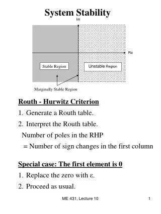
Renewable Energy Systems for Power Stability
560 likes | 699 Vues
Exploring modeling and economics of wind energy systems, emphasizing on sustainable power production and grid integration. Includes details on wind turbine design, farm development, and global trends.

Renewable Energy Systems for Power Stability
E N D
Presentation Transcript
ECEN 667 Power System Stability Lecture 26: Renewable Energy Systems Prof. Tom Overbye Dept. of Electrical and Computer Engineering Texas A&M University, overbye@tamu.edu
Announcements • Read Chapter 9 • Final is as per TAMU schedule. That is, Friday Dec 8 from 3 to 5pm here
Renewable Resource Modeling • With the advent of more renewable generation in power systems worldwide it is important to have correct models • Hydro systems have already been covered • Solar thermal and geothermal are modeled similar to existing stream generation, so they are not covered here • Coverage will focus on transient stability level models for wind and solar PV for integrated system studies • More detailed EMTP-level models may be needed for individual plant issues, like subsynchronous resonance • Models are evolving, with a desire by many to have as generic as possible models
Growth in Wind Worldwide Source: Global Wind 2016 Report, Global Wind Energy Council 4
Growth in Wind Worldwide Source: Global Wind 2016 Report, Global Wind Energy Council 5
Vestas Wind Systems Stock Price • Vestas’s stock has increased by more than 15times from their 2012/2013 lows! Their pricefell significantlyin Novemberdue to increasedcompetitionin wind powermarkets 6
Growth in US Wind • Production tax credit of $24/MWh being phased out • 100% in 2016, 80% in 2017, 60% in 2018, 40% in 2019 7 Source: American Wind Energy Association 2017 Third Quarter Market Report
2016 Installed Capacity by State:Texas Continues to Dominate! 8 Source: American Wind Energy Association 2017 Third Quarter Market Report
Wind Farm and Wind-Related Plant Locations http://gis.awea.org/arcgisportal/apps/webappviewer/index.html?id=eed1ec3b624742f8b18280e6aa73e8ec 9
State Renewable Portfolio Standards Texashas a goalof 10 GWby 2025,but thathas alreadybeen achieved(by morethan double!) Image source: dsireusa.org (see for updated information) 10
US Wind Resources 11 Source: http://www.windpoweringamerica.gov/wind_maps.asp
Global Wind Speed 50m Map http://www.climate-charts.com/World-Climate-Maps.html#wind-speed 12
Wind Map Texas– 80m Height 13 https://windexchange.energy.gov/files/u/visualization/image/tx_80m.jpg
Power in the Wind • The power in the wind is proportional to the cube of the wind speed • Velocity increases with height, with more increase over rougher terrain (doubling at 100m compared to 10m for a small town, but only increasing by 60% over crops or 30% over calm water) • Maximum rotor efficiency is 59.3%, from Betz' law • Expected available energy depends on the wind speedprobability densityfunction (pdf) 14
Wind Turbine Height and Size The currentlargest windturbine bycapacity isthe VestasV164 whichhas a capacityof 8 MW, a height of 220 m,and diameterof 164 m. 15 Source: cdn.arstechnica.net/wp-content/uploads/2016/11/6e9cb9fc-0c18-46db-9176-883cbb08eace.png
Extracted Power • WTGs are designed for rated power and windspeed • For speeds above this blades are pitched to operate at rated power; at furling speed the WTG is cut out 16
Example: GE 1.5 and 1.6 MW Turbines • Power speed curves for the GE 1.5 and 1.6 MW WTGs • Hub height is 80/100 m; cut-out at 25 m/s wind Source: http://site.ge-energy.com/prod_serv/products/wind_turbines/en/15mw/index.htm 17
Wind Farms (or Parks) • Usually wind farm is modeled in aggregate for grid studies; wind farm can consist of many small (1 to 3 MW) wind turbine-generators (WTGs) operating at low voltage (e.g. 0.6kV) stepped up to distribution level (e.g., 34.5 kV) 18 Photo Source: www.energyindustryphotos.com/photos_of_wind_farm_turbines.htm
Economies of Scale • Presently large wind farms produce electricity more economically than small operations • Factors that contribute to lower costs are • Wind power is proportional to the area covered by the blade (square of diameter) while tower costs vary with a value less than the square of the diameter • Larger blades are higher, permitting access to faster winds, but size limited by transportation for most land wind farms • Fixed costs associated with construction (permitting, management) are spread over more MWs of capacity • Efficiencies in managing larger wind farms typically result in lower O&M costs (on-site staff reduces travel costs) 19
Wind Energy Economics • Most of the cost is in the initial purchase and construction (capital costs); current estimate is about $1690/kW; how much wind is generated depends on the capacity factor, best is about 40% 20 Source: www.awea.org/falling-wind-energy-costs
Offshore Wind • Offshore wind turbines currently need to be in relatively shallow water, so maximum distance from shore depends on the seabed • Capacityfactors tendto increaseas turbinesmove furtheroff-shore Image Source: National Renewable Energy Laboratory 21
Offshore Wind Installations The first US offshore wind, Block Island (Rhode Island)with 30 MW, became operational in December 2016; CapeWind in Massachusetts was just officially cancelled this month Source: EIA August 14, 2015 and dwwind.com/project/block-island-wind-farm/ 22
Offshore: Advantages and Disadvantages • All advantages/disadvantages are somewhat site specific • Advantages • Can usually be sited much closer to the load (often by coast) • Offshore wind speeds are higher and steadier • Easier to transport large wind turbines by ship • Minimal sound impacts and visual impacts (if far enough offshore), no land usage issues • Disadvantages • High construction costs, particularly since they are in windy (and hence wavy) locations • Higher maintenance costs • Some environmental issues (e.g., seabed disturbance) 23
Types of Wind Turbines for Power Flow and Transient Stability • Several different approaches to aggregate modeling of wind farms in power flow and transient stability • Wind turbine manufacturers provide detailed, public models of their WTGs; these models are incorporated into software packages; example is GE 1.5, 1.6 and 3.6 MW WTGs (see Modeling of GE Wind Turbine-Generators for Grid Studies, version 4.6, March 2013, GE Energy) • Proprietary models are included as user defined models; covered under NDAs to maintain confidentiality • Generic models are developed to cover the range of WTGs, with parameters set based on the individual turbine types • Concern by some manufacturers that the generic models to not capture their WTGs' behavior, such as during low voltage ride through (LVRT)
Types of Wind Turbines for Power Flow and Transient Stability • Electrically there are four main generic types of wind turbines • Type 1: Induction machine; treated as PQ bus with negative P load; dynamically modeled as an induction motor • Type 2: Induction machine with varying rotor resistance; treated as PQ bus in power flow; induction motor model with dynamic slip adjustment • Type 3: Doubly Fed Asynchronous Generator (DFAG) (or DFIG); treated as PV bus in power flow • Type 4: Full Asynchronous Generator; treated as PV bus in power flow • New wind farms (or parks) are primarily of Type 3 or 4
Generic Modeling Approach • The generic modeling approach is to divide the wind farm models by functionality • Generator model: either an induction machine for Type 1 and 2's or a voltage source converter for Type 3 and 4 • Reactive power control (exciter): none for Type 1, rotor resistance control for Type 2, commanded reactive current for Type 3 and 4 • Drive train models: Type 1 and 2 in which the inertia appears in the transient stability • Aerodynamics and Pitch Models: Model impact of changing blade angles (pitch) on power output
Wind Turbine Issues • Models are designed to represent the system level impacts of the aggregate wind turbines during disturbances such as low voltages (nearby faults) and frequency deviations • Low voltage ride through (LVRT) is a key issue, in which the wind turbines need to stay connected to the grid during nearby faults • Active and reactive power control is also an issue
Low Voltage Ride Through (LVRT) • The concern is if during low voltages, such as during faults, the WTGs trip, it could quickly setup a cascading situation particularly in areas with lots of Type 3 WTGs • Tripping had been a strategy to protect the DFAG from high rotor currents and over voltages in the dc capacitor. • When there were just a few WTGs, tripping was acceptable • Standards now require specific low voltage performance Image from California ISO presentation
Type 3: Doubly Fed Asynchronous Generators (DFAG) • Doubly fed asynchronous generators (DFAG) are usually a conventional wound rotor induction generator with an ac-dc-ac power converter in the rotor circuit • Power that would have been lost in external rotor resistance is now used • Electrical dynamics aredominated by the voltage-source inverter, which has dynamics muchfaster than the transientstability time frame Image Source: Figure 2.1 from Modeling of GE Wind Turbine-Generators for Grid Studies, version 4.6, March 2013, GE Energy
Overall Type 3 WTG Model Transient stabilitymodels are transitioning Image Source: WECC Type 3 Wind Turbine Generator Model –Phase II, January 23, 2014, WECC TSS
Type 3 Converters • A voltage source converter (VSC) takes a dc voltage, usually held constant by a capacitor, and produces a controlled ac output • A phase locked loop (PLL) is used to synchronize the phase of the wind turbine with that of the ac connection voltage • Operates much faster than the transient stability time step, so is often assumed to be in constant synchronism • Under normal conditions the WTG has a controllable real power current and reactive power current • WTG voltages are not particularly high, say 600V
Type 3 WT3G Converter Model Network interface is a Norton currentin parallel with a reactance jX"
Type 3 Converters • Type 3 machines can operate at a potentially widely varying slip • Example, rated speed might be 120% (72 Hz for a 60 Hz system) with a slip of -0.2, but with a control range of +/- 30% • Control systems are used to limit the real power during faults (low voltage) • Current ramp rate limits are used to prevent system stress during current recovery • Reactive current limits are used during high voltage conditions
Aerodynamics • Type 3 and 4 models have more detailed models that directly incorporate the blade angle, so a brief coverage of the associated aerodynamics is useful • The power in the wind is given by Modeling of GE Wind Turbine-Generators for Grid Studies, version 4.6, March 2013, GE Energy
Aerodynamics • The Cp(q,l) function can be quite complex, with the GE 1.5 curves given below If such a detailed curve is used, the initialization is from the power flow P. There are potentially three independentvariables, vw, q and w. One approach is to fix w at rated (e.g., 1.2) and q at qmin Source: Modeling of GE Wind Turbine-Generators for Grid Studies, version 4.6, March 2013, GE Energy
Simplified Aerodynamics Model • A more simplified model is to approximate this curve as
Type 3 Example Case • Previous WSCC case, with the same line 6 to 9 fault, is modified so gen 3 is represented by a WT3G, WT3E, WT3T, and WT3P Graph at left shows azoomed (2 second)view of the gen 3 real power output, with the value falling to zero during the fault, and then rampingback up
Type 3 Example Case • Below graphs show the response of the WTG speed and blade angle
Type 4 Converters • Type 4 WTGs pass the entire output of the WTG through the ac-dc-ac converter • Hence the system characteristics are essentially independent of the type of generator • Because of this decoupling, the generator speed can be as variable as needed • This allows for different generator technologies, such as permanent magnet synchronous generators (PMSGs) • Traditionally gearboxes have been used to change the slow wind turbine speed (e.g., 15 rpm) to a more standard generator speed (e.g., 1800 rpm); with Type 4 direct drive technologies can also be used
Example: Siemens SWT-2.3-113 • The Siemens-2.3-113 is a 2.3 MW WTG that has a rotor diameter of 113m. It is a gearless design based on a compact permanent magnet generator • No excitation power, slip rings or excitation control system Image: www.siemens.com/press/pool/de/pressebilder/2011/renewable_energy/300dpi/soere201103-02_300dpi.jpg
Type WTG4 Model Very similar to the WTG3, except there is no X"
Type 4 Reactive Power Control Also similar to the Type 3's, as are the other models
Solar Photovoltaic (PV) • Photovoltaic definition- a material or device that is capable of converting the energy contained in photons of light into an electrical voltage and current • Solar cells are diodes, creating dc power, which in grid applications is converted to ac by an inverter • For terrestrial applications, the capacity factor is limited by night, relative movement of the sun, the atmosphere, clouds, shading, etc • A ballpark figure for Illinois is 18% • "One sun" is defined a 1 kw/m2,which is the maximum insolation the reaches the surface of the earth (sun right overhead)
US Annual Insolation The capacityfactor isroughly thisnumberdivided by24 hoursper day
US Solar Generated Electricity https://upload.wikimedia.org/wikipedia/commons/4/4e/US_Monthly_Solar_Power_Generation.svg 49
Solar PV can be Quite Intermittent Because of Clouds Intermittencycan be reducedsome whenPV is distributedover a larger region; keyissue is correlationacross an area Image: http://www.megawattsf.com/gridstorage/gridstorage.htm 50