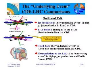
Underlying Technologies of Internet: Point-to-Point WANs and Rollout Project
Learn about the various types of interconnected networks in the Internet, including LANs, Point-to-Point WANs, and Switched WANs. Explore the implementation and workings of Point-to-Point WANs, DSL services, cable modems, T1/T3 service, and SONET. Understand the use of PPP protocol for point-to-point connections.

Underlying Technologies of Internet: Point-to-Point WANs and Rollout Project
E N D
Presentation Transcript
Ch 3: Underlying Technologies (remainder) Lecture #5 Project 1 rollout today – posted after lecture Course Dissemination Approach Vote Lecture
Internet – Underlying Technologies • Recall the various types of interconnected networks comprising the Internet: LANs, Point-to-Point WANs and Switched WANs • We have covered LANS: Ethernet, Token Ring, Wireless and FDDI Ring • Let’s cover the Point-to-Point WANs • Point-to-Point WANS • Connect devices via a public network line (ie. telephone company) • Telephone company – physical layer • Point-to-Point WAN – data link layer and up • Company services provided to make the connection: • Modem (modem to switching station to ISP) • DSL • Cable Modem • T Lines (ie. T1, T3) • SONET (optical carriers) Lecture
Telephony/56K Modem Digital Signal Analog Signal Digital Data Sampled 8000 times per sec with 8 bits per sample (1 bit for control) = 56 kps Lecture
Ranges changed for 4th Book Ed What does POTS stands for ?? P-to-P: DSL – Digital Subscriber Line • DSL – a set of technologies used to provide high-speed data service over copper wires that connect between the central office and local residences/businesses without expensive repeaters. • How is DSL implemented ? – high-speed DIGITAL WAN between COs – link between subscriber and the network is analog (becoming more and more digital though) • How does DSL work ? – divides the given bandwidth into 3 bands and offer phone service on one band and up and down stream traffic on the other 2 – phone service can occur with NO interruptions. Lecture
P-to-P: Other DSL Services • RADSL – rate adaptive asymmetric DSL – scales back the speed of ADSL based on the quality of the wire and distance between the CO and user. • Side Note: A newer version of ADSL called Universal ADSL (or UADSL) is being deployed in an attempt to standardize ADSL to a set of standard speeds – speeds vary across the Country • HDSL – high bit rate DSL – an digital alternative to T-1 analog service (T-1 contains multiple high-speed analog lines) • SDSL – symmetric DSL – same as HDSL however only 1 line is provided (is full-duplex) • VDSL – very high bit rate DSL – similar to ADSL however, in addition to using twisted-pair, coaxial and fiber-optic can be used in getting a much higher bit rate Lecture
P-to-P: Cable Modem • Still talking about point-to-point WANS • Uses the cable TV network • How does it work ?. some of the bandwidth dedicated to television signals is used for data traffic. • How does it work ?. The data signals are modulated into sine waves and placed on analog channels • How does it work ?. Typically, the BW in a neighborhood (or certain proximity) is shared (like a LAN in an office). Therefore, you never know if you have access to all of the BW. The more people using cable modems the worst the performance. • Some cable companies can dedicate some BW for phone service therefore offering voice, video/TV and data services on one cable • Cable modems are faster than computer modems because they are not limited by the 3000 Hz BW of the telephone line • The newer cable systems uses digital cable boxes and digital networks can send/receive data on separate digital channels • (draw picture of typical cable/video network – briefly explain history) Lecture
P-to-P: T1/T3 Service • Transport carriers originally designed for voice (672 circuits ???). • Typical “long haul” or “back bone” network – also used to interconnect WANs we mentioned • T1 line can send 8000 193-bit frames in one second • T3 line can send 224,000 193-bit frames in one second or be treated as 28 T1 lines (we called this a channel T1) • Fractional T lines – several customers sharing a T1 line – their data is multiplexed onto a single T1. Lecture
P-to-P: SONET • SONET means Synchronous Optical Networks – it’s a standard that defines a high-speed fiber-optic data carrier. • Electrical signals (called STSs – synchronous transport signals) are converted to light or optical signals (called optical carriers) • Comes in different rates, OC-1, OC-3, OC-9 ….. OC-48 ….OC-192 • The lowest data rate for SONET (OC-1) is greater than a T3’s data rate – Wow ! Lecture
PPP frame • To make a point-to-point connection, a protocol is needed at the data link layer (there are multiple protocols) • Well known protocol called PPP (point-to-point protocol) is used • PPP is the protocol of choice when connecting IP networks over telephone lines • Protocol – tells what type of data is in the data field • Data field – actual data • FCS – frame check sequence – used for error detection • Flag – bounds the PPP frame • Address – broadcast address (recall a point-to-point connection) • Control – frame sequencing info could go here – although most LANS don’t need a sequence number on frames (no routing) We also have LCP and NCP. Link Control Protocol – the PPP’s data field carry info regarding the mgmt of the link itself.Network Control Protocol – provides PPP the ability to carry actual IP packets in it’s data field. Lecture
Internet – Underlying Technologies • Internet is comprised of LANs, Point-to-Point WANs and Switched WANs • We have covered LANS: Ethernet, Token Ring (not in book), Wireless and FDDI Ring (not in book) • We have covered Pt-to-Pt WANs: Telephony Modem, DSL, Cable/Modem, T-Lines and SONET • We will cover Switched WANs: X.25, Frame Relay and ATM Lecture
Reminder • Quickly illustrate going from LAN-to-LAN via WAN Lecture
SWITCHED WANS • Switched WAN - a mesh of point-to-point networks connected via switches • Unlike LANS – multiple paths are needed between locations • Unlike LANS – no direct relationship between Tx and Rx • Paths are determined upfront and theses paths are used to send and receive (multiple paths for reliability and restoration) – recall that LANS uses Tx/Rx addresses to make the connection • Uses Virtual Circuit concept • 3 well known Switch WANs:X.25, Frame Relay and ATM Lecture
X.25 • Developed in 1970 – the first switch WAN – becoming more and more obsolete • X.25 standard describes all of the functions necessary for communicating with a packet switching network • Divided into 3 levels: • (1) physical level – describes the actual interfaces • (2) frame level – describes the error detection and correction • (3) Packet level – provides network-level addressing (constant BW efficiency problem – but it worked) Because X.25 was developed before the Internet, the IP packets are encapsulated in the X.25 packet when you have an IP network on each side of a X.25 backbone Lecture
Frame Relay Network • Designed to replace X.25 • Have higher data rates than X.25 • Can handle “bursty data” by allocating BW as needed versus dedicating constant chucks of BW • Less error checking and overhead needed – more reliable and efficient • DTE – data terminating equipment – devices connecting users to the network (ie routers) • DCE – data circuit-terminating equipment – switches routing the frames through the network Frame Relay Switches in the yellow cloud Lecture
Switched WANs - ATM • ATM – Asynchronous Transfer Mode – is a cell relay protocol • Objectives of ATM (upfront initiative): • Make better use of high data rate transmission (ie. fiber optics) • WAN between various types of packet-switch networks that will not drive a change in the packet-switch networks • Must be inexpensive (no barrier to use) – want it to be the international backbone • Must be able to support the existing network hierarchies – local loops, long-distance carriers, etc..) • Must be connection-oriented (high reliability) • Make more hardware oriented versus software oriented in speeding up rates (explain this – circuit vs software) • Cell – small unit of data of fixed size – basic unit of data exchange • Different types of data is loaded into identical cells • Cells are multiplexed with other cells and routed • By having a static size, the delivery is more predictable and uniform Lecture
ATM multiplexing • ATM uses asynchronous time-division multiplexing – cells from different channels are multiplexed • Fills a slot with a cell from any channel that has a cell Lecture
Architecture of an ATM network • User access devices (called end points) are through a user-to-network interface (UNI) to switches in the network • The switches are connected through network-to-network interfaces (NNI) Lecture
Virtual circuits • Connections between points are accomplished using transmission paths (TP), virtual paths (VP) and virtual circuits (VC). • TP – all physical connections between two points • VP – set of connections (a subset of TP) (ie. Highway) • VC – all cells belonging to a single message follow the same VC and remain in original order until reaching Rx (ie. Lane) • The virtual connection is defined by the VP and VC identifiers Lecture
An ATM cell Lecture
ATM layers • ATM Standard defines 3 layers: Application Adaptation Layer, ATM Layer and Physical Layer • Application Adaptation Layer – facilitates communications between ATM networks and other Packet-Switched Networks by taking the packets and fitting them into fixed-sized CELLS. • At the Rx, cells are re-assembled back into packets • Keep in mind that any type of transmission signal can be packaged into an ATM cell: data, voice, audio and video - makes ATM very powerful • Application Adaptation Layer is divided into 4 parts: • AAL1- handles the constant bit rate cases (ie. voice, real-video) • AAL2- handles variable bit rate cases (ie. compressed voice, non-real-time video, data) • AAL3/4 – handles connection-oriented data services (ie VoIP) • AAL5 – handles connectionless-oriented protocols (ie. TCP/IP) Lecture
ATM layers • ATM Layer in general – routing, flow control switching & multiplexing • ATM Layer – going down – accepts bytes segments and translate to cells • ATM Layer – going up – translate cells back into byte segments – keep in mind that a node can be acting as both an intermediate and Rx node (and Tx) • ATM Physical Layer – translate cells into a flow of bits (or signals) and vice versa Lecture
ATM LAN architecture • ATM LAN speeds: 155 Mbps and 622 Mbps • 3 design approaches: (1) pure ATM LAN, (2) legacy ATM LAN and (3) combo of (2) and (3) • Pure ATM LAN: ATM switch is used to connect the stations in a LAN (uses VPI/VCI versus destination/source addresses) Lecture
Legacy ATM LAN architecture • Use an ATM LAN as a backbone – frames staying with in a certain network need not be converted • Frames needing to cross to another LAN must be convertedand ride the ATM LAN Lecture
Mixed ATM LAN Architecture Lecture
Internet – Underlying Technologies • Recall that the Internet is comprised of LANs, Point-to-Point WANs and Switched WANs • We covered LANS: Ethernet, Token Ring, Wireless and FDDI Ring • We covered Switched WANs: X.25, Frame Relay and ATM • We covered Pt-to-Pt WANs: Telephony Modem, DSL, Cable/Modem, T-Lines and SONET How are these networks connected ? Lecture
CONNECTING DEVICES Lecture
Repeater Operates at the physical layer – layer 1 Receives the signal and regenerates the signal in it’s original pattern A repeater forwards every bit; it has no filtering capability Is there a difference between a regen or repeater and an amp ?? Lecture
Repeaters d For the architecture above, will a signal ever traverse through more than 2 repeaters ? Lecture
Hubs Hub – multi-port repeater Typically used to create a physical star topology Also used to create multiple levels of hierarchy For bus technology type networks, hubs can be used to increase the collision domain Lecture
Bridge • Operates at both the physical and data link layers • At layer 1, it regenerates the signal. At layer 2, it checks the Tx/Rx physical address (using a bridge table) • Example Below: • If packet arrives to bridge-interface #1 for either of the 71….. stations, the packet is dropped because the 71…. Stations will see the packet • If packet arrives to bridge-interface #2 for either of the 71….. stations, the packet is forwarded to bridge-interface #1 With such an approach, the “bridged” network segments will acted as a single larger network What is a “smart” bridge ?? Lecture
Routers • Is a 3-layer device: (1) at layer 1, regen the signals, (2) at layer 2, check physical address and (3) at layer 3, check network addresses • Routers are internetworking devices • Routers contain a physical and logical/IP address for it’s interfaces (repeaters/bridges don’t) • Routers only act on the packets needing to pass through • Routers change the physical address of the packets needing to pass through (repeaters/bridges don’t change physical addresses) Show example where a decision is needed d d Lecture
Routing example • Routers can change the physical address of a packet • Example: as a packet flow from LAN 1 to LAN 2 • In LAN 1, the source address is the Tx’s address and the destination address is the Router’s interface address • In LAN 2, the source address is the Router’s interface address and the destination address is the Rx’s address LAN 1 LAN2 Lecture
You are a High Priced Network Consultant Marketing Dept Engineering Dept (Super Computer) Manufacturing Dept (Robots) d They want all departments to communicate with one another;you want the network to maintain top performance – which design would you recommend ? Which devices would you recommend for empty circles ? – the least cost solution is the best solution Lecture
Note: Lectures for Exam 1 just ended. We now start lectures for Exam 2 Lecture
Chapters 4 & 5 Addressing Lecture
IP ADDRESSING (Ch 4) Lecture
IP Addresses • Internetworking Protocol (IP) of the Network Layer is responsible for uniquely identifying all devices and connections on the Internet • The unique identifier is called an IP address • IP address consist of 32 bits (for version 4) • Keep in mind that, if a single device had multiple connections to the Internet, you would need an IP address for each connection • Address space is 232 = 4,294,967,296 32-bit addresses • In theoretical terms, 4,294,967,296 connections can be made to the Internet (not really true in real life) Lecture
0111 0101 1001 0101 0001 1101 1110 1010 75 95 1D EA 75951DEA IP Addresses • The IP Address has 3 notations: Binary, Dotted-decimal and Hexadecimal • Binary: 4 Octets: 01110101 10010101 00011101 11101010 • Dotted-Decimal (or dot notation): • For Dotted-Decimal, each number can range from 0 to 255 • Hexadecimal: Lecture
EXAMPLES Change the following IP address from binary notation to dotted-decimal notation: 10000001 00001011 00001011 11101111 Solution 129.11.11.239 Change the following IP address from dotted-decimal notation to binary notation: 111.56.45.78 Solution 01101111 00111000 00101101 01001110 Find the error, if any, in the following IP address: 111.56.045.78 Solution There are no leading zeroes in dotted-decimal notation (045). Change the following IP addresses from binary notation to hexadecimal notation: 10000001 00001011 00001011 11101111 810B0BEF16 Solution Lecture
IP Addresses: Classful Addressing • When IP addressing was first started, it used a concept called “classful addressing”. A newer concept called “classless addressing” is slowly replacing it though. • Regarding “classful addressing”, the address space is divided into five classes: A, B, C, D and E. Lecture
Finding the class in binary notation Finding the class in decimal notation Lecture
EXAMPLES Solution Find the class of the address: 00000001 00001011 00001011 11101111 The first bit is 0. This is a class A address. Solution Find the class of the address: 11000001 10000011 00011011 11111111 The first 2 bits are 1; the third bit is 0. This is a class C address. Solution Find the class of the address: 227.12.14.87 The first byte is 227 (between 224 and 239); the class is D. Lecture
Netid and hostid • A, B and C class-addresses are divided into network id and host id • For Class A, Netid=1 byte, Hostid = 3 bytes • For Class B, Netid=2 bytes, Hostid = 2 bytes • For Class C, Netid=3 bytes, Hostid = 1 byte Lecture
Blocks in class A • Class A has 128 blocks or network ids • First byte is the same (netid), the remaining 3 bytes can change (hostids) • Network id 0 (first), Net id 127 (last) and Net id 10 are reserved – leaving 125 ids to be assigned to organizations/companies • Each block contains 16,777,216 addresses – this block should be used by large organizations. How many Host can be addressed ???? • The first address in the block is called the “network address” – defines the network of the organization • Example • Netid 73 is assigned • Last address is reserved • Recall: routers have addressees Lecture
Blocks in class B • Class B is divided into 16,384 blocks (65,536 addresses each) • 16 blocks are reserved • First 2 bytes are the same (netid), the remaining 2 bytes can change (hostids) • For example, Network id 128.0 covers addresses 128.0.0.0 to 128.0.255.255 • Network id 191.225 is the last netid for this block • Example • Netid 180.8 is assigned • Last address is reserved • Recall: routers have addresses Lecture
Blocks in class C • Class C is divided into 2,097,152 blocks (256 addresses each) • 256 blocks are reserved • First 3 bytes are the same (netid), the remaining 1 byte can change (hostids) • For example, Network id 192.0.0 covers addresses 192.0.0.0 to 192.0.0.255 Lecture
Class D addresses are used for multicasting; there is only one block in this class. Class E addresses are reservedfor special purposes; most of the block is wasted. Lecture
Network Addresses The network address is the first address. The network address defines the network to the rest of the Internet. Given the network address, we can find the class of the address, the block, and the range of the addresses in the block Given the network address 17.0.0.0, find the class, the block, and the range of the addresses. The class is A because the first byte is between 0 and 127. The block has a netid of 17. The addresses range from 17.0.0.0 to 17.255.255.255. Solution Given the network address 132.21.0.0, find the class, the block, and the range of the addresses. The class is B because the first byte is between 128 and 191. The block has a netid of 132.21. The addresses range from 132.21.0.0 to 132.21.255.255. Solution Given the network address 220.34.76.0, find the class, the block, and the range of the addresses. The class is C because the first byte is between 192 and 223. The block has a netid of 220.34.76. The addresses range from 220.34.76.0 to 220.34.76.255. Solution Lecture
REMINDER: Go Over Converting Binary to Decimal and Vice Versa Lecture
Converting Number Systems - Review Base-10 The decimal number system is based on power of the base 10. For example, for the number 1259, the 9 is in the 10^0 column - 1s column the 5 is in the 10^1 column - 10s column the 2 is in the 10^2 column - 100s column the 1 is in the 10^3 column - 1000s column 1259 is 9 X 1 = 9 + 5 X 10 = 50 + 2 X 100 = 200 + 1 X 1000 = 1000 ----- 1259 Base-2 (Binary) The Binary number system uses the same mechanism and concept however, the base is 2 versus 10 The place values for binary are based on powers of the base 2: … 2^7 2^6 2^5 2^4 2^3 2^2 2^1 2^0 128 64 32 16 8 4 2 1 Lecture