Download
1 / 58
600 likes | 768 Vues
SMS & NET Operated Monitoring and Control system. By: Mansour Alramlawi Mahmoud Alalawi Mohammed Alfeqawi Jalal Alroumi Hamdi Joudeh Supervisor: Dr. Hatem Elaydi. Introduction. Rapid Growth in technology. Fields of Industry, Communications, Control, Internet technology ….. And more.

E N D
SMS & NET Operated Monitoring and Control system By: Mansour Alramlawi MahmoudAlalawi MohammedAlfeqawi JalalAlroumi HamdiJoudeh Supervisor: Dr. HatemElaydi
Introduction • Rapid Growth in technology. • Fields of Industry, Communications, Control, Internet technology ….. And more. • You can be anywhere anytime. You want to know Anything happening everywhere.
One of the Benefits Remote Monitoring & Controlling Home Applications Space Applications Industrial, Natural Resources, Agriculture and others.
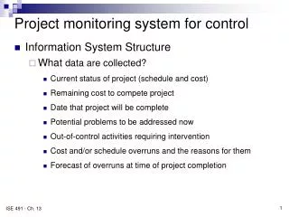
Functionality • As a monitoring & control system for simple applications.
Functionality • As part of a large DCS.
Features PIC MCU Based Stand Alone System SMS & Net Operated Title Blocks Approach
System Block Diagram • Saves time and effort. • Easier to upgrade. • Allows reuse of blocks.
SMS • SMS stands for( Short Message Service). Features of SMS: • 1-can be Sent and Read at Any Time. • 2-can be Sent to an Offline Mobile Phone. • 3-Supported by 100% GSM Mobile Phones .
Connect SMS to MCU Type of connection • M-Bus • -half duplex • -Runs at bit rate of 9600 bps. • F-Bus • -full duplex • -Runs at bit rate of 115,200 bps.
AT command • commands are the application layer of MBUS or FBUS commands • AT commands work on devices that have a built-in GSM modem
AT command Vs. F-Bus Send message AT command AT+CMGS 972599378166 F-Bus
So why F-Bus • F-Bus work with all kind of mobile devices especially old devices. • AT commands don’t work with devices that don’t have built in GSM modem.
Microcontroller PIC18F4550
Microcontroller program Receive Message: • Transfer order to central PIC • Check sender number • If correct get order from message • store message frame • Wait until message receive • synchronize the USART in the phone with microcontroller
Send Message Send message • Transfer input to mobile through F-Bus • If input change, change message frame according to number of input • Monitoring incoming data from central PIC
Network support in our system • First time to support stand alone Ethernet. • No software needed to run the system. • No extra hardware to connect with PC. • Flexibility. • Very short start up time. • Can be improved to connect to the internet.
enc28j60 Advantages • Supporting 10base_T 10 Mbps speed. • Simpler interfacing with Microcontroller. • connectable via SPI. • Need only 5 pins to connect with PIC. • Attractive price.
Microcontroller of module • Pic18F452 is installed. • Full support for SPI module. • Sufficient ram space. • support enough speed for its duty.
WEB Page programming • WEB page is programmed as HTML code. • Html code is saved in MCU as characters array in PIC Memory. • The code Can be edited in the MCU to meet the coming request .
Control operation Step 1 Step 2 Step 3 Step 4 Sending control order ON/OFF Change the state of the output port Modify the HTML page Return modified page
Monitoring operation • Refreshing the value of input. • Auto refresh in the web page. • Changing the unit color if input status is changed.
Connecting with internet What we need ? • Public IP address. • Web-server with known IP. • Reliable security.
Why wireless? 1- Easy to deploy. 2- Easy to distribute. 3- No infrastructure required.
Wireless controller • The encoder and decoder are used in interfacing the TX and RX to the MCU and in addressing different devices.
Addressing • The Encoder allows address assignment. • Each device has its own address.
Interference • Interference occurs since the channel is a half duplex
Sending Control data Control data
Requesting monitoring data Monitoring data
Introduction • Task: - To get the other blocks working all together. - To organize the flow of data among blocks. • Features: - The heart of the system. - Acts like Master while the other PICs act like slaves.
Warehouse Approach • Main Concept: - Using the Central PIC as a warehouse. - Whenever a block has data to deliver or needs data, it stores it in or takes it from the warehouse. - Each block has its own functionality and its own manner in requesting data.
Types of Connection • Two types of connection are used: 1- Parallel Connection: To connect the Central PIC to the SMS PIC. 2- USART module: To connect the Central PIC to both, the Wireless PIC and the Ethernet PIC.
Busy Line • Other blocks may communicate with the Central Block at the same time. • Busy line is used to indicate that the Central PIC is in the middle of a session with one of the PICs.