Download
1 / 35
350 likes | 623 Vues
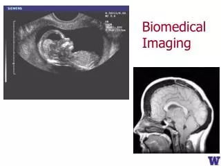
Advanced Biomedical Imaging Lecture 4. Dr. Azza Helal A. Prof. of Medical Physics Faculty of Medicine Alexandria University. Radiographic Image Quality. Image quality parameters (photographic properties) Density Contrast Resolution (Image details)

E N D
Advanced Biomedical Imaging Lecture 4 Dr. Azza Helal A. Prof. of Medical PhysicsFaculty of MedicineAlexandria University
Radiographic Image Quality Image quality parameters (photographic properties) • Density • Contrast • Resolution (Image details) • Signals / Noise (Grainy image) • Lack of artifacts
1. Density • Overall blackening of the image. • If the image is too dark, it has too much density, overexposed. • If the image is too light, it lacks density, underexposed.
2. Contrast • Difference between densities of adjacent structures • Controlled by energy of the beam. µα1/E3 • Depends on tissue and type of film • High contrast is too black & white. • Low contrast is too gray.
Contrast & Density • Contrast & density are controlled by exposure factors and film processing.
X-ray Exposure Factors • Settings controlled by the operator used to produce the radiograph. • Will influence the amount of patient exposure • Type of x-ray machine and screen film combination will impact the exposure factors.
Exposure factors Increasing voltage (kV)increases maximal energy of x-rays produced, & ↑ penetration of beam,film exposure, making the film darker, ↓ pt dose & ↓ exp time but ↓ contrast. (obese pt) Increasing mAs increases the amount of x-rays produced, exposure, and signals, making the film darker, ↓ exp time. Film dose is α Kv4 mAS.
A small focal spot produces sharper images. A large focal spot can tolerate more heat but increase image unsharpness. (see lecture 3). Exp time: ↓ by ↑ Kv & large focal spot (↑blurring)
mAs • Product of mA times the exposure time • 100 mA @ .10 seconds = 10 mAs • 200 mA @ 0.05 seconds = 10 mAs • As long as the product of the mA and time are the same, the exposure should be the same if the Ma and timer calibration is accurate.
mAs determines the quantity of x-ray photons. • mAs establishes the densityon the image. • Density is the blackness of the image. • It takes a change of 25% to 30% in mAs to make a significant change in the density of the image.
Change the mAs and Change the Density of the Image • The center image has the mAs decreased by 25%. Density is decreased. • Image on the right has the mAs increased by 25% above the image on the left. Density is increased.
Wrong mAs This image is under exposed. Not enough mAs was used & density reduced This image is overexposedfor the patella. Too much mAs was used & density increased.
30-50 Rule • Relatively large changes in mAs are needed to change the density of the image. • It takes a change of 20 to 30% to make any change in the density of the image. • It needs a change by 50% to make a significant change. • This is the 30-50 Rule
Changing mAs • As mAs increased; • the density of the image changes from under exposed to over exposed.
Over exposed • This was taken with 60 mAs. • To correct the density of the image, 30 mAs would be used. • So mAs reduced by 50%.
Under exposed • This image was taken at 30 mAs. • To darken the image, 60 mAs would be used. • To correct the density of the films double the mAs.
Grid Ratio and Frequency • The higher the ratio and frequency, the more radiation is needed to produce the image. • Low grid ratio is limited to low kVp. A 5:1 grid is limited to below 90 kVp. • High ratio grids can be used up to 125 kVp.
Grid Ratio and Frequency • Low frequency grids have prominent grid lines on image. • They are used in true Buckies. • The grid moves during the exposure to blur the lines. • High frequency grids produce almost invisible lines and do not need to move during the exposure.
Grid Ratio and Technique • For imaging of lumbar spine without the grid: • 8 mAs @ 74 kVp used • 15-16 mAs @ 74 kVp used to produce the image with the 5:1 grid. (doubling mAs) • The conversion factor would be 2 for adjusting the mAs for the 5:1 grid
Grid Ratio and Technique • The 5:1 grid required doubling the mAs. • The conversion factor is determined by dividing the new mAs by the old mAs. • What would be the conversion factor for the 10:1 grid? Old mAs = 8 New mAs = 40
No Grid Used • Lumbar Spine needs the use of a grid. why? • There is too much scatter radiation due to the size of the body part • Exposure factors needed to be adjusted to visualize this area.
Low Ratio & Frequency Grid • For the A-P Lumbar Spine, a 5:1 with 80 grid lines will remove much of the scatter radiation. • Going from Non-Grid to a 5:1 ratio requires doubling the mAs. • Grid lines are very noticeable.
High Ratio & Frequency Grid • A 10:1 grid with 100 lines will provide excellent clean-up of scatter radiation. • Grid lines are nearly invisible. • But, requires 5 times more radiation.
Grid Cut-off • When high frequency and ratio focused grids are used, • the lead strips must be perfectly aligned with the primary beam. • A minor misalignment will result in the grid removing primary radiation. • Misalignment of more than 2° will result in grid cutoff.
Grid Cut-off • Is the density of the image of both knees the same? • This is an example of grid cut-off. • Some of the primary beam is being removed by the grid.
Grid Cut-off causes • If grid lines are not parallel to primary radiation due to • tube being too close • too far from the grid,
If the tube is angled against the grid lines. • If grid is not perpendicular to the beam (most common problem).
If grid is backwards, only center of beam will pass though the grid. • So proper alignment must be maintained.
Air-gap Vs Grids • Using air gap not grid, • Radiation exposure reduced five folds • With no loss of image quality.
3. Resolution Resolution (image details): Minimum distance between two points that can be recognized as being separate.
4. Noise Noise (grainy image): variation in no of x ray photons absorbed
5. Lack of artifacts Artifact is the appearance of signal in an image location not representative of actual properties of object.
Questions • What are main parameters that control image quality? • Enumerate causes of grid cut-off? • Define contrast, density and artifact?