BNL ERL and frequency choices
230 likes | 329 Vues
BNL ERL and frequency choices. Ilan Ben-Zvi. In this presentation:. Introduction The eRHIC ERL design The R&D ERL Frequency Choice Summary. The ARDD of the Collider-Accelerator Department.

BNL ERL and frequency choices
E N D
Presentation Transcript
BNL ERL and frequency choices Ilan Ben-Zvi
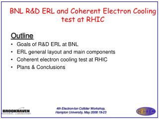
In this presentation: • Introduction • The eRHIC ERL design • The R&D ERL • Frequency Choice • Summary
The ARDD of the Collider-Accelerator Department • The Accelerator R&D Division (ARDD) of C-AD engages in medium-term R&D related to the mission of ONP and provides expertise and support to short term accelerator R&D. • The ARDD is the site of a unique combination of expertise and facilities: • Electron cooling of unique nature, such as the Coherent electron Cooling and bunched-beam electron cooling for cooling Low Energy RHIC. • Superconducting RF for highly specialized applications such as high-current ERL, storage ring applications and SRF electron guns. • Laser photocathodes, polarized and high QE non-polarized. • The ARDD has a HEP funded component (LARP, ATF, Muon Accelerator), which benefits the ONP program, e.g. crab cavities, and vice versa – the HEP program benefits from the capabilities within NP. • The expertise and intellectual interchange with HEP units greatly enhances the capabilities of the ARDD.
From the EICAC Report on Accelerator R&D Priorities (C-AD is carrying out this research based on these recommendations) • eRHIC highest priority: • High current (e.g. 50 mA) polarized electron gun • Demonstration of high energy – high current ERL • Beam-Beam simulations for EIC • Polarized 3He production and acceleration • Coherent electron cooling • eRHIC high priority: • Compact loop magnets • Development of eRHIC-type SRF cavities • eRHIC medium Priority: • Crab cavities (funded by HEP in LARP group) Complex projects!
NS-FFAG eRHIC: Rapidly evolving! 11 turns 2 FFAG rings 50 mA Current scheme, 10 GeV
COHERENT ELECTRON COOLING • The CeC is a novel technique to cool stored ion beam which combines the best features of stochastic cooling and electron cooling. Such an effective cooling technique can be used to cool RHIC proton beams at full energy, and is a must for any version of EIC. • Competitive ONP R&D funding for CeC (M&S only, k$): • FY11 FY12 FY13 FY14 FY15 FY161488 1280 1410 1727 370 272
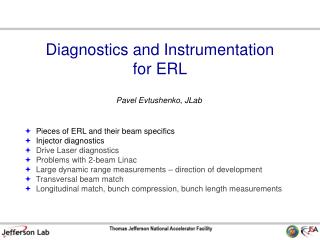
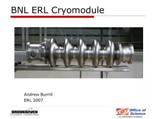
Energy Recovery Linac (ERL) • The R&D ERL is aimed at testing ERL issues for eRHIC and related projects, such as Coherent electron Cooling of RHIC. The current of 300 mA is required by eRHIC cavities. • The ERL incorporates originally developed state-of-the-art SRF laser-photocathode electron gun and a high-current, heavily damped acceleration cavity, the first such designed and built for ERL service.
POLARIZED GUN • We are doing R&D, funded primarily by LDRD, to develop a high-current (50 mA), high-polarization electron gun for eRHIC. • The principle we are aiming to prove is funneling multiple independent beams from 20 cathodes. • External review was carried out in 2012.
Superconducting RF cavity HOM ports FPC port • A five-cell 703.8 MHz SRF cavity (BNL3) is optimized for high-current linac applications. • Reduced peak surface magnetic field -> reduced cryogenic load. • Three antenna-type couplers will be attached to a large diameter beam pipes at each end of the cavity and will provide strong HOM damping while maintaining good fill factor for the linac.
HOM damping HOM high-pass filter • A two-stage high-pass filter rejects fundamental frequency, but allows propagation of HOMs toward an RF load. • 1st HOM is at 0.82 GHz (for the 704 MHz cavity). • Total HOM power to extract is ~11 kW per cavity through 6 HOM dampers.
Frequency Choice Considerations • Bunch structure of eRHIC • Bunch length and energy spread • Beam breakup • SRF losses • RF power efficiency • Cost and complexity considerations • The considerations to be presented point towards a lower frequency ERL cavities, as will be shown in the following. The current choice is:
Bunch structure and the frequency choice • To have uniform bunch pattern w/o large transients, the RF frequency has to be a multiple of the RHIC bunch repetition frequency (9.38 MHz) times twice the number of ERL passes (e.g. 11). • It can be 413 MHz. • By having all electron acceleration passes in the tunnel, we may have a ~0.95μS gap, enough to avoid ion accumulation and the fast ion instability. • The gap is also very useful to provide diagnostic electron bunches. • We are driven towards a lower frequency by a number of effects: • BBU • Energy spread due to RF wave curvature affecting polarization • HOM power and energy spread due to cavity wake potential • Energy spread due to other wake fields • R56 errors & path length errors affecting energy spread • The choice of 413 MHz provides satisfactory results.
Effect of transient voltage kick • When an electron bunch with charge q passes a cavity with a voltage V, it will remove (or add) an energy ΔU from the cavity, where ΔU=qV=5.3(nC).30.3(MV)=0.162(J) This corresponds to a transient voltage drop per cavity of ΔV/V=0.5ΔU./U=1.1.10-4 The transient voltage step for 11 passes is then 1.2.10-3, in a highly repetitive pattern. • Note that the transient voltage fraction is proportional to f 2 • The RHIC hadron beam has 111 of 120 filled RF buckets at ~9.38 MHz • The e-beam pattern has 111 full energy bunches, each circulating the long path going around the 3.8 km RHIC tunnel 22 times (11 acceleration and 11 deceleration passes). • Extra (non-colliding electron bunches) may be introduced in the gap to provide diagnostics.
Energy spread due to wake fields • Lower frequency allows us to increase the bunch length (RF curvature, always a limit). • This in turn reduces the various wake field effects. • Cavity wake and resistive wall are the dominant effects for eRHIC • Surface roughness is negligible for eRHIC. • CSR shielding is easier for longer bunches. Cavity Resistive Wall Roughness Thanks to A. Fedotov CSR
E. Pozdeyev B E x Instability mechanism and threshold Beam establishes a feedback that can become unstable. The threshold is approximately 1 accel.-1 decel., 2D N accel.-N decel., 1D • Ithis inversely proportional to the HOM mode frequencies • Fewer HOMs (due to larger, fewer cavities) in linac.
Multi-bunch BBU due to HOM of Cavities • 11 passes ERL, 412.8 MHz • BBU threshold current are found by simulation with code written by E. Pozdeyev. • Even without HOM frequency variation, the threshold current, 106 mA, is more than a factor of 2 above the designed current, 50 mA. • With rms HOM frequency variation of 3.10-3, the BBU threshold current is 457 mA. R/Q of HOM Q_ext of HOM Courtesy of Y. Hao and W. Xu
BCS resistance as a function of temperature Operating at a lower frequency can save refrigeration power! n T(ºK) Residual resistance: ~1 n possible
RF Power Efficiency • Class-F solid state amplifiers • More choices in transistor material at lower frequencies. • Efficiency increases with lower frequency. • RF power is required just for microphonics control.
RF power for microphonics and size • Assume h~l, Δf/f=δmax/l, f~1/l (h is a transverse dimension of a bar) • Then the frequency deviation per unit force is proportional to Δf~l-3 • The tuning power is given by Prf=2πUΔf and U~l3 • Thus the RF power required for microphonics control should be independent of the cavity frequency. • However, with larger cavities we need fewer amplifiers!
Cost and complexity The cost of the niobium material is a small fraction of the linac cost, minimal effect on cost. Complexity is reduced with lower frequency. Fewer welds per voltage gain for a larger cavity. ILC. M. Harrison, P5 A. Favale, IPAC11
Summary • At the Accelerator R&D Division of C-AD we are pursuing the design and critical R&D for and ERL based eRHIC. • The eRHIC design is evolving rapidly, using innovative ideas such as a funneling polarized gun, SRF ERL, Coherent electron Cooling and various design features, the latest being the use of a NS-FFAG. • We made choices for the frequency of the ERL based on constraints given by the RHIC bunch structure and circumference as well as a general push towards the lowest plausible ERL frequency. • Some of the considerations leading to the choice of frequency were given above.