Download
1 / 53
540 likes | 1.15k Vues
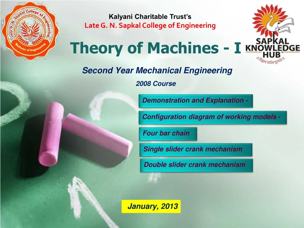
Kalyani Charitable Trust’s Late G. N. Sapkal College of Engineering. Theory of Machines - I. Second Year Mechanical Engineering 2008 Course. January, 2013. Demonstration and Explanation -. Configuration diagram of working models -. Four bar chain. Single slider crank mechanism.

E N D
Kalyani Charitable Trust’s Late G. N. Sapkal College of Engineering Theory of Machines - I Second Year Mechanical Engineering 2008 Course January, 2013 Demonstration and Explanation - Configuration diagram of working models - Four bar chain Single slider crank mechanism Double slider crank mechanism
Theory of Machines - I MACHINE A machine is a mechanism or a collection of mechanisms which transmits force from the source of power to the resistance (load) to be overcome, and thus performs useful mechanical work. MECHANISM A mechanism is a combination of rigid or resistant bodies so shaped and connected that they may move upon each other with definite relative motion. • BASIC CONCEPTS • KINEMATIC LINK AND TYPES OF KINEMATIC LINKS • KINEMATIC PAIR AND TYPES OF KINEMATIC PAIRS • TYPES OF CONSTRAINED MOTIONS • KINEMATIC CHAIN • INVERSION
Theory of Machine Branch of science deals with Study of relative motion between various parts of machine and forces act on them. Classified into two types kinematics and dynamics.
Link- A member or combination of members, connecting Other members and having motion relative to them. • Types of links • Rigid link- examples: Crank, Connecting rod, Piston • Flexible link-examples: Belt and chain drive, Springs • Fluid link-Liquid used in Hydraulic press , Jacks and • breaks of Automobiles • Types of rigid links • Binary link • Ternary link • Quaternary link
Constrained Motions 1. Completely constrained motion: • Completely constrained motion is a type of constrained motion in which relative motion between the links of a kinematic pair occurs in a definite direction by itself, irrespective of the external forces applied.
2. Incompletely constrained motion: • If the motion between the pair can takes place in more than one direction. • Depending on the direction of external forces applied, the shaft may slide or turn (or do both) inside the circular hole.Read more
Partially (or successfully) constrained motion: • A kinematic pair is said to be partially or successfully constrained if the relative motion between its links occurs in a definite direction, not by itself, but by some other means. A good example of successfully constrained motion is piston reciprocating inside a cylinder in an internal combustion engine. • Examples: Foot Step Bearing.
Kinematic pair and types • Def.: kinematic pair is a combination of two kinematic links that have relative motion with respect to each other. • Based on the nature of contact between the pairing elements • Lower Pair • Higher Pair • Based on the type of mechanical constraint (or mechanical contact) • Self Closed Pair • Force Closed Pair • Based on the type of relative motion between the elements of the pair • Sliding Pair • Rolling Pair • Turning Pair • Screw Pair (or Helical Pair) • Cylindrical Pair • Spherical Pair
Based on the nature of contact between the pairing elements • Lower Pair : A kinematic pair is said to be a lower pair if the links in the pair have surface or area contact between them.Examples Shaft rotating in bearing, Nut Turning in Screw.Along with a cylinder, a piston forms a lower pair • Higher Pair: A higher pair is a kinematic pair in which the links have point or line contact. Ball bearings, cam and follower are examples of higher pair. Examples: Cam and follower,Ball Bearings
Based on the type of mechanical constraint: • 1. Self Closed Pair: A pair is said to be self closed if the links in the pair have direct mechanical contact, even without the application of external force. • 2. Force Closed Pair A kinematic pair is said to be force closed if the links in the pair are kept in contact by the application of external forces. A good example of this type of pair is ball and roller bearings.
Based on the type of relative motion between the elements of the pair • Sliding Pair: As the name suggests, a sliding pair is a kinematic pair in which each element has sliding contact with respect to the other element. Some good examples of sliding pairs are piston inside a cylinder, spur gear drive and square bar in a square hole.
Rolling Pair: In a rolling pair, one element undergoes rolling motion with respect to the other • Examples: Wheel rolling on a • flat surface, Ball Bearing • 3. Turning Pair: In a turning pair, one link undergoes turning motion relative to the other link. Example is a shaft with collars in a circular hole.
Screw pair: • A screw pair consists of links • that have both turning and • sliding motion relative to • each other. • Cylindrical Pair: • A cylindrical pair is a kinematic pair in which the links undergo both • rotational and translational motion • relative to one another. • Example: A solid cylindrical bar inside a hollow shaft. • 6. Spherical Pair: • In a spherical pair, a spherical link turns inside a fixed link. • A spherical pair has three degrees of freedom. • Examples: Ball and socket joints, Pen stand.
Kinematic chain • Combination of kinematic pairs in such a way that each link forms a part of two pairs and motion of each relative to other is definite. • Relation between no. of pairs and no. of links L=2P-4 • Relation between no. of joints and no. of links J= 3/2L-2 L.H.S > R.H.S, Chain is Locked L.H.S =R.H.S, Chain is Constrained L.H.S< R.H.S, Chain is unconstrained
DOF or Mobility • The number of inputs which need to be provided in order to create a predictable output • The number of independent coordinates required to define its position • DOF in Planar Mechanisms Gruebler’s Equation=F=3(n-1)-2j Kutzbach Equation=F=3(n-1)-2j-h If F=-1, Mechanism is redundant, preloaded structure If F=0, No movability, Structure. If F=1 One inpute gives unit output
Degrees of Freedom As DOF 3 position 3D Space = 6 DOF 3 orientation In robotics: DOF = number of independently driven joints positioning accuracy computational complexity cost flexibility power transmission is more difficult
10 9 8 7 9 8 6 5 6 5 4 3 DOF = 3(L – 1) – 2J1 – J2 = 3(12-1) -2(15) = 3 3 2 1 2 Degrees of Freedom (DOF) – trench hoe Number of links, L = 12, Number of one DOF joints, J1 = 12 (pins) + 3 (slider) = 15, 11, 12 Number of two DOF joints, J2 = 0 11 12 10 7 4 3 hydraulics are used to control the position of the bucket. 1 Mechanical & Aerospace Engineering Dept., SJSU
1 DOF = 3(L – 1) – 2J1 – J2 = 3(7-1) – 2(7) – 1 = 3 1 1 Degree of Freedom (DOF) - example Number of links, L = 7, Number of one DOF joints, J1 = 6 (pins) + 1 (slider) = 7, Number of two DOF joints, J2 = 1 (fork joint) Three input sources are needed to control the mechanism Fork Joint 4 3 2 Spring 5 Slider 6 7 Mechanical & Aerospace Engineering Dept., SJSU
L = 3, J1 = 3, J2 = 0 DOF = 3(3-1) - 2(3) = 0 Redundant support 3 L = 5, J1 = 6, J2 = 0 4 DOF = 3(5-1) - 2(6) = 0 2 5 Paradoxes Two rollers in contact, no slipping Mechanical & Aerospace Engineering Dept., SJSU
Inversion –An inversion is created by grounding a different link in the kinematic chain Grashoff,s Condition –Is a simple relationship that predicts the rotation behavior or rotatability of a four linkage’s inversion based only on the link lengths S+L<or = P+Q •S = length of shorter link •L=length of longest link •P=length of one remaining link •Q=length of the other remaining link
Various links in Four Bar Mechanism –Ground •Any link or links that are fixed with respect to the reference frame –Crank •A link which makes a complete revolution and is pivoted to ground –Rocker •A link which has oscillatory (back and forth) rotation and pivoted to ground –Coupler •A link which has complex motion and is pivoted to ground
Grashof Condition –For the class I case: S+L< P+Q •Ground either adjacent to the shortest link and you get a crank-rocker •Ground the shortest link and you will get a double-crank •Ground the link opposite the shortest and you will get a Grashof double-rocker –For the Class II case: S+L> P+Q •All inversion will be triple-rockers in which no link can fully rotate –For Class III: S+L=P+Q •All inversion will be either double-cranks, or crank-rocker
Theory of Machines - I • FOUR BAR CHAIN - (FOUE LINK PLANAR MECHANISMS) • Simplest of all mechanisms. • Use and application in machines and mechanical devices is very extensive. • This will also familiarize with many commonly used terms and ideas related to • mechanisms. • Large variety of motions is possible with only four links (in fact with only three • moving links) with different combination s of kinematic pairs and different • inversions of the chain. • Four lower pairs are required to connect the four links in four link mechanism. • There are types of kinematic pairs in plane kinematic chains – revolute pairs and • prismatic pairs • Possible combinations are RRRR, RRRP, RRPP, RPRP • There are four possible inversions for each kinematic chain.
Theory of Machines - I • Demonstration and explanation of configuration diagram of working models based on • Four bar chain • Single slider crank mechanism • Double slider crank mechanism • For various link positions Ranges of Motion of a Four Bar Linkage (Grashof’s Criterion)
Theory of Machines - I Four Bar Chain First Inversion Crank and Rocker Mechanism Example BEAM ENGINE
Theory of Machines - I Four Bar Chain Second Inversion Double Crank Mechanism (Drag Link Mechanism) Example WHEELS OF LOCOMOTIVE
Theory of Machines - I Four Bar Chain Third Inversion Double Lever Mechanism (Double Rocker Mechanism) Example ACKERMAN STEERING GEAR
Theory of Machines - I Single Slider Crank Chain First Inversion Reciprocating Engine Mechanism Example RECIPROCATING AIR COMPRESSOR
Theory of Machines - I Single Slider Crank Chain Second Inversion Oscillating Cylinder Engine Mechanism Example
Theory of Machines - I Single Slider Crank Chain Second Inversion Crank and Slotted Lever Mechanism Example SHAPING MACHINE
Theory of Machines - I Single Slider Crank Chain Third Inversion Whitworth Quick Return Mechanism Example SHAPING MACHINE
Theory of Machines - I Single Slider Crank Chain Third Inversion Example ROTARY ENGINE
Theory of Machines - I Single Slider Crank Chain Forth Inversion Example HAND PUMP
Theory of Machines - I Double Slider Crank Chain First Inversion Example ELLIPTICAL TRAMMEL
Theory of Machines - I Double Slider Crank Chain Second Inversion Example SCOTCH YOKE MECHANISM
Theory of Machines - I Double Slider Crank Chain Third Inversion Example OLDHAM COUPLING
Theory of Machines - I Report for the experiment A1 Title - Introduction - Four bar chain - Inversion, kinematic diagram, model Single slider crank mechanism - Inversion, kinematic diagram, model Double slider crank mechanism - Inversion, kinematic diagram, model references -
Straight line motion mechanism • Exact straight line mechanism Peaucellier mechanism Harts mechanism Scott- Russel Mechanism • Approximate straight line mechanism Grass- hopper’s mechanism Watt’s mechanism Robert’s mechanism
Exact straight line motion mechanisms made up of turning pairs: • Let O be a point on the circumference of a circle of diameter OP. Let B is a point on OA (chord), such that From similar triangles OAP and OBQ, But OP and OQ are constant then OA X OB = Constant. Hence the point B moves along a straight path BQ which is perpendicular to OP.
Peaucellier mechanism 1. It consists of 8 links i.e. a fixed link OO1 and the straight links O1A, OC, OD, AD, DB, BC and CA are connected by turning pairs. 2. The pin at A is constrained to move along the circumference of a circle. 3. AC = CB = BD = DA; OC = OD; and OO1 = O1A
2. Hart’s mechanism: 1. It consists of six links i.e. a fixed link OO1 and straight links O1A, FC, CD, DE and EF are connected by turning pairs. 2. The pin at A is constrained to move along the circumference of a circle. 3. FC = DE; and CD = EF; 4. The points O, A and B divide the links FC, CD and EF in the same ratio.
1. Watt’s mechanism: It is a crossed four bar chain mechanism and in steam engines it guides the piston rod to have an approximate straight line motion.
2. Modified Scott-Russel mechanism: 1. In this mechanism AP is not equal to AQ and points P & Q are constrained to move in the horizontal and vertical directions. 2. It forms an elliptical trammel, so that any point A on PQ traces an ellipse with semi major axis AQ and semi minor axis AP. OA = ((AP) 2) / (AQ).
3. Grasshopper mechanism: 1. It is the modification of modified Scott-Russel’s mechanism with the difference that Point P does not slide along straight line. 2. It is a four bar mechanism and all the pairs are turning pairs. 3. In this, O and O1 are fixed and link OA oscillates about O. 4. OA = ((AP) 2) / (AQ).
Roberts mechanism: 1. It is a four bar mechanism, which, in its mean position, has the form of a trapezium. 2. The link OA and O1B are of equal length and OO1 is fixed. 3. The point Q trace out an approximately straight line.
Steering gear mechanism • The steering gear mechanism is used for changing the direction of two or more of the wheel axles with reference to the chassis. • Types of steering gear mechanism Davis steering gear mechanism Ackermann's steering gear mechanism