Download
1 / 54
540 likes | 554 Vues
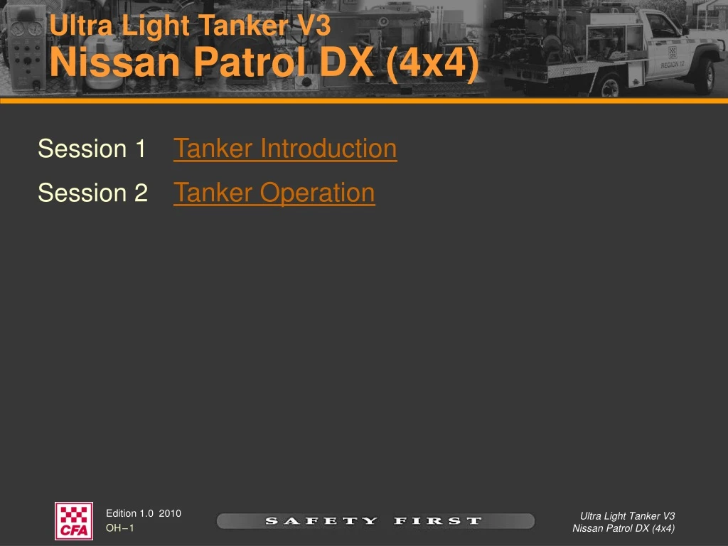
Get introduced to the ultra light tanker with a 3.0L turbo diesel engine and learn about its operation. Discover features like bucket seats, air conditioning, manual transmission, and more.

E N D
Ultra Light Tanker V3Nissan Patrol DX (4x4) Session 1 Tanker Introduction Session 2 Tanker Operation
Session 1:Description • Two seater with bucket seats and air conditioning • 3.0 litre, four cylinder, turbo diesel engine • 5 speed manual gearbox • Manual locking free wheeling front wheel hubs • Limited slip differential - rear axle • Water tank capacity 550 litres • GAAM Mk 70 single stage pump driven by a Hatz 1B40 10.0 HP diesel engine.
Session 1:Turbo Charger • To prevent potential damage to the turbocharger you should: • allow the engine to idle for a period of three minutes prior to shutting down.This allows the turbo charger to reduce speed and also allows time for the turbine casing to cool down • never rev the engine immediately on start up.Allow a few seconds for oil to reach all parts of the engine & turbine bearings.
Session 1:Transmission • 5 speed manual transmission • Two speed transfer case – High and Low range 4WD. Note: The vehicle must be stationary in order to select low range four wheel drive.
To unlock hub, turn centre control anti- clockwise until stop. To lock hub, turn centre control clockwise until stop. Session 1:Free Wheel Hubs The tanker is fitted with free wheel hubs.
Session 1:Free Wheel Hubs Important • Both hubs must be either “locked” or “unlocked” • Hubs must be locked prior to selecting four wheel drive • It is recommended that the hubs are always left engaged as a safety measure.
Session 1:Brakes • Front - ventilated disc brakes • Rear - drum brakes • Load sensing brake valve - regulates the brake distribution percentage between the front and rear brakes • Park brake. Actuates the rear drum brakes.
Session 1:Fire Pump • The pump is a GAAM Mk 70 single stage centrifugal, driven by a single cylinder air cooled Hatz Hatz 1B40 10HP diesel engine • Rated maximum flow of pump is 850 litres/minute @ 100kPa** • Rated pump Duty Point 500 litres/minute @ 500 kPa** • The pump engine diesel fuel tank is continuously filled from the vehicle’s fuel tank. **Note:Theoretical figures taken from the pump curves. They do not allow for plumbing friction losses and suction lift.
Session 1:Stowage Suction hose and wet hose locker
Session 1:Stowage Rake hoes (2)
Session 1:Stowage 38 mm fill line Hydrant
Session 1:Stowage Firelighters (2)
Session 1:Stowage Shovel and Pulaski tool
Session 1:Safety • Driver and passenger airbags • Driver and passenger seat belt pre-tensioners • Airbag compliant bull bar • Reversing camera and monitor. Monitor controls: • Power button • Brightness Up/Down buttons • Channel button. The Reverse camera is input 3 and input 4 is an A.V input (eg view output from a digital camera on the monitor).
Session 2:Siren Control – Hazard CS200 • “1” – The roof mounted LED light bar and front emergency hazard lights; • “2” – The roof mounted LED light bar, front emergency hazard lights and flashing headlights; and • “3” – The roof mounted LED light bar and front emergency hazard lights, flashing headlights and siren. Pressing the button cycles through the different siren tones available. Button inactive Up arrow – inactive. Left arrow – activates left alley light. Right arrow – activates right alley light. Bottom position – Cancels the active function.
Session 2:Pump Controls Compound and delivery pump pressure gauges Fire pumpstart button Pump throttle (twist) Pump stop button
Session 2:Tanker Connections 30m x 19mm live hose reel 2 x 38mm deliveries 75 mm hard suction (Storz) 38mm tank fill (Storz)
Session 2:Water Tanker Fill Points Two water tank fill points: • Overhead – 150mm filler on the top of the RHS front of the tank. Fill from an overhead hydrant • 38mm filler coupling on the rear of the tank.
Session 2:Water Level Indicator Liquid level sight gauge
Session 2:Diaphragm Priming Pump Primer isolation valve Diaphragm Priming Pump
Session 2:Quenchmaster Class A Foam System The Quenchmaster SP301 around the pump proportioning system: • induces foam concentrate into the suction side of the pump. • is designed to operate between 600 kPa and 1000 kPa. • the metering valve selects the percentage of foam concentrate to be added to the water and the proportioning is between 0.1% and 1%. Note: Application data for wildfire: • 0.1% to 0.3% maximum • Use normal branches to apply • “Wetter is better”.
Session 2:Foam Concentrate • Foam concentrate is stored in a 20 litre plastic drum on the nearside rear of the appliance
Session 2:Operating the Pump – Electric Start Start Pump • Slightly turn the throttle dial out (1/2 turn) from the stop position. • Press the Fire Pump Start button • Adjust the throttle dial to obtain the desired pump pressure.
Session 2:Operating the Pump – Shutdown Shutdown Pump • Adjust the throttle dial so the engine is idling. • Fully press or turn the throttle dial until the engine stops.
Session 2:Operating the Pump – Manual Start ManuallyStartPump • Slightly turn the throttle dial out (1/2 turn) from the stop position. • Pull on the manual rope start handle with two hands in one quick and firm action • Adjust the throttle dial to obtain the desired pump pressure.
Session 2:Operating the Pump – Fuel Note - Pump engine fuel • The vehicles ignition (accessories) must be on for the pump engine fuel transfer pump to operate. • If the vehicle’s ignition is off, or the “aux. fuel pump” light illuminates, the pump engine fuel tank is not being fuelled. Therefore, if the pump engine fuel tank is already full, there will only be 1-2hrs of pumping remaining depending on flow rate output.
Session 2:Draughting Water – Prepare to Prime • Remove the suction hose from top locker and attach orange float with chain assembly. • Remove blank 75mm Storz cap on the 75mm inlet • Attach the hard suction hose.
2 Session 2:Draughting Water – Prepare to Prime • Close tank supply valve (GREEN) - valve no. 2. • Close tank recirculation valve (pump to tank fill line) - valve no. 4 4
1 Session 2:Draughting Water – Prepare to Prime • Open priming pump Isolation valve – valve no. 6. (Valve shown closed.) • Open hard suction line – valve no. 1. 6
Session 2:Draughting Water – Prime the Pump • Slightly turn the throttle dial out (1/2 turn) from the stop position. (Note: do not start pump engine at this stage). • Operate hand priming pump until a good stream of water free of air shows from the priming pump discharge line.
6 Session 2:Draughting Water – Prime the Pump • Close pump priming valve – valve no. 6
Session 2:Draughting Water – Deliver Water • Start the pump engine. • Pressure gauge should register approx. 300 kpa minimum (adjust pump throttle as required). • Ensure pump is satisfactorily primed by showing water at a delivery valve.
4 Session 2:Draughting Water – Deliver Water • Open tank recirculation valve – valve no. 4 slowly whilst watching pressure gauge to ensure prime is maintained. • When tank indicator shows full turn pump off.
Session 2:Shutting Down from Draughting Shutdown pump • Reduce engine revs to idle. • Fully press or turn the throttle dial until the engine stops.
Session 2:Shutting Down from Draughting Restore pump to operate from tank supply • Close tank recirculation valve - valve no. 4. • Close hard suction line valve no. 1 (GREEN)
Session 2:Shutting Down from Draughting Restore pump to operate from tank supply • Disconnect suction hose assembly and restow. • Replace the blank 65mm Storz cap on the 65mm inlet. • Start pump and check that pump delivers water.
Session 2:Boosting from Reticulated Supply Prepare to boost • Assume the pump is running and delivering water from the tank as the initial supply. • Set the standpipe to the ground ball and flush as required. • Connect the 65 mm filler length to the hydrant.
2 1 Session 2:Boosting from Reticulated Supply Supply water • Attach the 65mm filler length using the 75mm to 65mm Storz adaptor . • Charge hose with water. • Open the 75mm inlet valve no. 1 (GREEN) • Close tank supply valve no. 2 (GREEN). • Adjust pump engine speed to provide required discharge pressure (300 kpa minimum). • Monitor supply line to ensure adequate water is being delivered to the pump.
Session 2:Boosting from Reticulated Supply Change back to tank supply • Open tank supply value no. 2 (GREEN). • Check pressure gauge. • Close 75mm inlet valve no.1. • Check for water delivery out of the pump. • Note: a one way valve is fitted to the tank supply line to prevent water from the hard suction line flowing into the tank and causing damage to the tank structure.
Session 2:Live Hose Reel Operation Before pulling hose off the reel • Note: Live hose reel supply valve should be in the OFF position except when in use • Unlock catch pin on reel frame. • Release over centre friction brake lever on the axle shaft.
Session 2:Live Hose Reel Operation Before pulling hose off the reel • Select appropriate branch from locker and fit to hose. • Turn supply valve ON.
Session 2:Live Hose Reel Operation Rewinding reel • Turn supply valve OFF. • Rewind hose onto reel in layers using the handle as supplied. (Locker NS1) • Lock pin into drum frame. • Re-apply friction brake on axle shaft to closed position. • Remove any branch fitted to hose and restow in locker.
Session 2:Class A Foam System – Produce foam Note: • Production of Class A Foam can only occur when using the TANK SUPPLY. When boosting from a reticulated supply a pressure differential cannot be obtained to allow around the pump proportioning to occur
Session 2:Class A Foam System – Produce foam Start pump • Start pump • Set delivery pressure to 600 kPa minimum.