CH-GEAR CUTTING OPERATIONS
CH-GEAR CUTTING OPERATIONS

CH-GEAR CUTTING OPERATIONS
E N D
Presentation Transcript
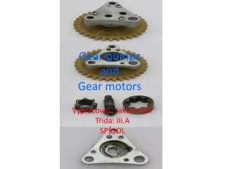
CH-GEAR CUTTING OPERATIONS Gear drives possess a very prominent role in mechanical power transmission. A gear is an important machine element which is used for transmission of power or motion or both from one shaft to the other. It is normally a round blank carrying projections or teeth along its periphery of a cylinder or a cone, or on elliptical discs which enable a positive drive. They are mounted on the axles or shafts and keyed to them. Gears are vastly employed to form mechanisms for transmission of power from one part to other in a machine and to effect change in speed or torque or both of one part with respect to other.
Selection of gears is governed by many factors such as- The relative position of the two shafts, the load or power they are expected to transmit, space limitation, running conditions, speeds to be employed and similar other factors. Methods of gear making Gear making is a highly specialized job.It is manufactured by the following 3 methods. 1.Casting 2.Rolling 3.Machining (i) Forming (ii)Template method (iii)Generating method
1.Casting: Cast iron gears are cast in sand moulds or permanent metal moulds. These gears are relatively rough, weak and inaccurate but the cost of production is very low. This method is therefore, used for large gears only. Small cast gears for light duty work are better produced by die casting, particularly of non-ferrous metals and alloys. These gears have sufficient accuracy and high surface finish. Plastic moulding is also used to produce gears of plastic materials for very light work. 2.Rolling: Hot rolling process is also used for making gears. In this the hot gear blank is rolled against a master gear to produce the desired teeth on its periphery. 3.Machining: It is the most widely used method of making gears. In this method, previously cast or forged gear blanks or those cut from bar stock, metal sheets and laminated plastics etc. are machined to produce the teeth of desired shape and size along their periphery.
There are 3 methods used for gear cutting or machining i). Forming, (ii)Template method (iii)Generating method i)Forming: The cutter used has the same form as the space between the teeth to be cut. The cutters used for this purpose on planer and shaper are single point tool, on milling machine a revolving multi tooth tool called cutter and on a broaching machine a broach. ii)Template method: The method is exclusively used on a machine called gear planer. In this the single point reciprocating tool is guided by a master template. This method is used actually for finishing the gear teeth which have been previously rough formed and is mostly employed for large and coarse pitch spur and bevel gears.
(iii)Generating method: In this method the cutting tool meshes with the gear blank and both rotate, the teeth being generated by the combined rolling motion of the two. Gear Hobbing Process: In this process the gear blank is rolled with a rotating cutter called hob. • A majority of involute gears are produced by this method. In operation the hob is rotated at a suitable speed and fed into the gear blank. The blank also rotates simultaneously and the speeds of the two are so synchronised that the blank rotates through one pitch distance for each complete revolution of the hob.
Comparison of hobbing with other generating processes: • Most of the different types of gears can be produced by all the generating processes: These processes can also be used for producing other shapes like splines, cams and gear sprockets etc. Out of all generating processes the hobbing method is most widely used for the following reasons : 1. It provides a continuous cutting operation and is,therefore faster and more accurate than the other generating processes. 2. The hobbing machines are smaller than the machines used in other processes since they involve only one type of motion of the cutter with respect to the blank. 3. The heat generated during the process is uniformly distributed over the work and the cutter and excessive heating of both is thus, avoided.
4. Long shafts and splines can be easily accommodated on hobbing machines. 5. Many gears, mounted on the same arbour, can be cut simultaneously. 6. Gap type harringbone gears can be generated only through hobbing. Gear finishing • The surface of gear teeth produced through shaping or generating process is not very accurate and properly finished. Such a surface results in a lot of ,noise, excessive wear, play or backlash amongst meshing teeth or sometime's in an ultimate failure of the gears in the drive. In order to overcome these, defects some finishing operations become necessary after the gears are produced. • Such operations make the gears quiet, dependable and smooth
running. The common finishing operations performed are the following 1.Shaving. 2. Burnishing. 3. Grinding. 4. Lapping. Gear shaving • It is a process of finishing gear teeth by running the gear at high speeds in mesh with a gear shaving tool which is in the form of a rack or pinion. The teeth of the shaving tool are hardened, accurately ground and their faces provided with serrations. These serrations form the cutting edges which actually provide a sort of scrapping operation on the mating faces of the gear to be finished.
The gear is pressed into contact with the shaving tool • and the latter rotated at high speed. The gear also rotates in mesh with the tool and is also reciprocated simultaneously. The shaving tool carries a little inclined teeth so that their axes can be crossed as the two come in contact this prevents the jamming of the two. The above relative motion of the gear and the shaving tool results in a highly finished surface on the gear teeth. When a rack type tool is used gear is mounted on the reciprocating arbor and is brought in mesh with a horizontal rack situated under it. The rack is reciprocated longitudinally at a high speed and the gear across it. The lengthwise movement of the rack type tool also rotates the gear.
Gear burnishing: • It is also a cold process for finishing the gear teeth and is employed on gears after cutting prior to hardening. The gear is mounted on a vertical reciprocating shaft in mesh with three hardened and ground burnishing gears . • One of these gears is power driven. The three gears fed into the cut gear and rotated through few turns in both the directions. This makes these gear teeth surfaces smooth and also imparts a little hardness to them. Gear grinding: Gear required to operate on high speeds and carry heavy loads are always hardened, which naturally implies a small distortion on the teeth flanks. In order to remove this distortion and have accurate profiles on the teeth for smooth running, grinding of gear teeth becomes essential. The two common methods used for grinding hardened gear teeth are(i) forming and (ii)generating.
In forming process the abrasive wheel is first trued to the required shape and size of the gear teeth. The work is mounted between the centers on an indexing head. The grinding wheel is rotated and the mounted gear reciprocated under it. After each stroke the grinding wheel is fed downwards till the required depth is reached. The gear is then withdrawn and indexed for the next tooth. In generating process the grinding is done by the flat face of the grinding wheel as the gear mounted on an arbor or mandrel, is rolled past the revolving wheel which is also reciprocated to cover the full working surfaces of a tooth. Alternatively a very large grinding wheel is used. Many gear grinding machines use a pair of grinding wheels to avoid the reciprocating action. When one tooth is finished the gear is indexed for the next tooth.
Gear Lapping • Those gears which are finish machined or shaved and then heat treated (hardened) are ultimately lapped to remove scale improve surface finish on the teeth and rectify small errors due to distortion during the hardening process. In this process the gear to be lapped is run under load in mesh with one or more cast iron toothed laps. Either an abrasive paste is introduced between the teeth or fine abrasive powder mixed in oil is made to flow through the teeth during the operation. A very negligible amount or almost no metal removal takes place during the operation. As such this process can not be used to correct the tooth profiles or dimensional inaccuracies. It helps in improving the surface finish. Many different types of it only helps in improving the surface finish. Many different types of machines have been developed to perform this operation. In one type the lap meshes with the gear mounted above it and drives the latter, the axis of the two being crossed.
One of the mating members is reciprocated axially. On some machines the lap is reciprocated and on others the gear is reciprocated so as to effect a uniform metal removal. Undercutting and its prevention: In generated gears having a very small number of teeth this defect occurs. This is actually a result of improper design. In such gears the involute profile of the tooth is discontinued below the pitch circle resulting in a wider gap in a wider gap between successive, teeth below the pitch circle. It is called 'under cutting'. This is due to the action of the corners of the teeth of the generating cutter on the profile of the gear teeth. There are 4 common methods of preventing this.
To increase the pressure angle, so as to move the interference point or base circle towards the centre of the gear. 2. To make stub teeth i.e., teeth having smaller addendum for a given pitch. 3. To reduce the addendum and increase the dedendum, in case of wheels having large number of teeth and vice versa in case of wheels having small number of teeth. 4. To reduce the depth of teeth slightly and increase the addendum. This is done, however, only when both the mating gears will have a small number of teeth.