Download
1 / 1
10 likes | 232 Vues
CAS 2012: "Introduction to Accelerator Physics” Universidad de Granada Facultad de Ciencias Políticas y Sociología 28 October - 9 November, 2012. IFMIF-EVEDA RF POWER SYSTEM. David Regidor, Moisés Weber (CIEMAT, Madrid, Spain). Introduction.

E N D
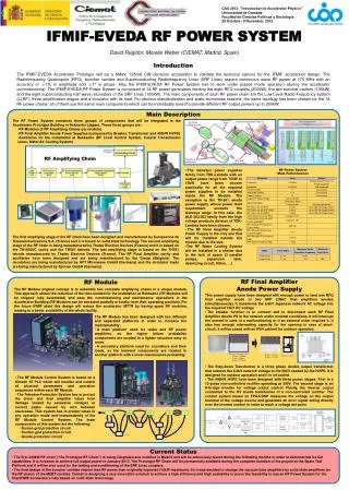
CAS 2012: "Introduction to Accelerator Physics” Universidad de Granada Facultad de Ciencias Políticas y Sociología 28 October - 9 November, 2012 IFMIF-EVEDA RF POWER SYSTEM David Regidor, Moisés Weber (CIEMAT, Madrid, Spain) Introduction The IFMIF-EVEDA Accelerator Prototype will be a 9MeV, 125mA CW deuteron accelerator to validate the technical options for the IFMIF accelerator design. The Radiofrequency Quadrupole (RFQ), buncher cavities and Superconducting Radiofrequency Linac (SRF Linac) require continuous wave RF power at 175 MHz with an accuracy of ±1% in amplitude and ±1º in phase. Also the IFMIF/EVEDA RF Power System has to work under pulsed mode operation (during the accelerator commissioning). The IFMIF/EVEDA RF Power System is composed of 18 RF power generators feeding the eight RFQ couplers (200kW), the two buncher cavities (105kW) and the eight superconducting half wave resonators of the SRF Linac (105kW). The main components of each RF power chain are the Low Level Radio Frequency system (LLRF), three amplification stages and a circulator with its load. For obvious standardization and scale economies reasons, the same topology has been chosen for the 18 RF power chains: all of them use the same main components which can be individually tuned to provide different RF output powers up to 200kW. Main Description • The RF Power System combines three groups of components that will be integrated in the Accelerator Prototype Building in Rokkasho (Japan). These three groups are: • RF Modules (2 RF Amplifying Chains per module) • RF Final Amplifier Anode Power Supplies (composed by Breaker, Transformer and 400kW HVPS) • Auxiliaries for the installation at Rokkasho (RF Local Control System, Coaxial Transmission Lines, Water/Air Cooling System) RF Amplifying Chain • The Genesys power supplies family from TDK-Lambda with an output power range from 750W to 15kW have been chosen practically for all the required power supplies to be installed inside the RF Module. The exception is the TH-561 anode power supply, whose power level requirement exceeds the Genesys range. In this case, the ALE 203/303 family from the high voltage products division of TDK-Lambda have been chosen. • The RF Final Amplifier Anode Power Supply is the only one that will be installed outside the module due to the size. • The RF Water Cooling System will be installed in a shelter due to the lack of space (3 parallel pumps, expansion tank, deionizing circuit, filters, …) RF Power System Main Performances The first amplifying stage of the RF chain have been designed and manufactured by Europeenne de Telecommunications S.A. (France) and it is based on solid state technology. The second amplifying stage of the RF chain is being manufactured by Thales Electron Devices (France) and it is based on the TH18526C cavity and the TH561 tetrode. The last amplifying stage is based on the TH781 tetrode manufactured by Thales Electron Devices (France). The RF Final Amplifier cavity and auxiliaries have been designed and are being manufactured by Iba Group (Belgium). The circulators are being manufactured by AFT Microwave GmbH (Germany) and the circulator loads are being manufactured by Spinner GmbH (Germany). External casing dimensions: Width <= 1900mm Depth = 1000mm Height = 1760mm Width = 1671mm Height = 1336mm Depth = 765mm RF Final Amplifier Anode Power Supply RF Module The RF Module original concept is to assembly two complete amplifying chains in a unique module. This approach allows the reduction of the time needed for the installation at Rokkasho (RF Modules will be shipped fully assembled) and ease the commissioning and maintenance operations in the Accelerator Building (RF Modules can be extracted partially or totally from their operating position). For the future IFMIF plant this design will reduce the accelerator MTTR by having spare RF modules, leading to a better availability of the whole facility. • This power supply have been designed with enough power to feed one RFQ final amplifier anode or two SRF LINAC final amplifiers anodes (simultaneously). It transforms the 6.6kV Japanese network AC voltage into the required 13kV DC voltage. • The breaker function is to connect and to disconnect each RF Final Amplifier Anode PS to the network under nominal conditions. It will interrupt the current in case of a malfunctioning or if an external order requires it. It also has enough interrupting capacity for the opening in case of short-circuit. It will be cased with an IP54 cabinet for outdoor operation. • The RF Module has been designed with two different and separated platforms in order to increase the maintainability: • A main platform used for racks and RF power amplifiers, so the higher failure probability components are located in a lighter structure easy to move. • A secondary platform used for circulators and their loads, so the heaviest components are located in another platform with a lower maintenance probability. • The Step-down Transformer is a three phase double output transformer that reduces the 6.6kV network voltage to the 500V needed by the HVPS. It is designed for outdoor operation and it is oil cooled. • The 400kW HVPS have been designed with three power stages. First is a 12-pulse non-controlled rectifier operating at 500V. The second stage is an H-bridge inverter for voltage output control. Finally, the inverter output connected to the HV anode transformer of a non-controlled rectifier. The control system based on FPGA/DSP measures the voltage on the output terminal of the voltage source and generates an error signal acting directly over the inverter control in order to reach a voltage set point. • The RF Module Control System is based on a Simatic S7 PLC which will monitor and control all physical parameters and operation sequences within each RF Module. • The Tetrodes Protection System has to protect the driver and final amplifier tubes from damage caused by excessive voltages or current peaks caused by arcs between electrodes. This system has to protect tubes in any operation mode and independently of the RF Module Control System. The main components of this system are the following: • Screen grid protection circuit • Control grid protection circuit • Anode protection circuit Current Status • The first 200kW RF chain (“the Prototype RF Chain”) is being integrated and installed in Madrid and will be extensively tested during the following months in order to demonstrate its full capabilities. It is foreseen to achieve full output power in January 2013. The Prototype RF Chain will be permanently available during the complete duration of the project at the Spain Test Platform and it will be also used for the testing and conditioning of the SRF Linac couplers. • The final design of the buncher cavities require less RF power than originally expected (16kW maximum). So it was decided to change the vacuum tube amplifiers by solid state amplifiers for the RF chains of the MEBT cavities. Ciemat is designing a very innovative solution to achieve a high efficiency and high scalability to prove the feasibility to use an RF Power System for the final IFMIF accelerators fully based on solid state technology.