Design and Implementation of a Low-Power Operational Amplifier for Health Monitoring Applications
500 likes | 618 Vues
This project outlines the design and implementation of a low-power CMOS operational amplifier (op-amp) suitable for health monitoring systems. It aims to achieve a gain of 250,000 V/V with a power consumption of 250 µW. The methodology includes formulating testing procedures for device characterization and generating data plots for datasheets. Various circuit topologies, including differential amplifiers and common source amplifiers, are explored. The project emphasizes low-power consumption and efficient device modeling, ensuring compatibility with modern mobile communication technologies.

Design and Implementation of a Low-Power Operational Amplifier for Health Monitoring Applications
E N D
Presentation Transcript
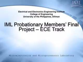
Electrical and Electronics Engineering InstituteCollege of EngineeringUniversity of the Philippines, Diliman IML Probationary Members’ Final Project – ECE Track Microelectronics and Microprocessors Laboratory
Overview Introduction Project Specifications Methodology
CurrentTrend LOW POWER Health Monitoring Mobile Comms Field Testing Introduction • Project Specifications• Methodology
ProjectObjectives • design & implement a CMOS op-amp topology for low-power application • formulate testing methodology • for device characterization • generating plots for datasheet • model bond wires Introduction • Project Specifications• Methodology
LowPowerIndustry 250,000 V/V gain 250 μW power consumption rail-to-rail input/output capability Introduction • Project Specifications• Methodology
Op-ampFeatures LPC661 by National Semiconductor Different Process! Introduction • Project Specifications• Methodology
Op-ampFeatures Different Topology! TSM27M2C by STMicroelectronics Bi-CMOS Process! Introduction • Project Specifications• Methodology
15,000 2.5 mW Design Constraints Minimum DC Gain (Av) Maximum Power Consumption Introduction • Project Specifications• Methodology
Design & Implementation 2-stage or Miller Common Source Amplifier Differential Amplifier Bias Circuit Introduction • Project Specifications• Methodology
Design & Implementation Differential Amplifier Group Transistors Derive Parameter Dependencies Introduction • Project Specifications• Methodology
1 2 3 Design & Implementation Differential Amplifier Transistor Pairs Introduction • Project Specifications• Methodology
Group Transistors Derive Parameter Dependencies Derive Parameter Dependencies Set Current Set Length Compute Widths Adjust Widths Size Resistor N Extract Parameters Met? Y Check Constraints End Design & Implementation Differential Amplifier Introduction • Project Specifications• Methodology
Design and Implementation Differential Amplifier Introduction • Project Specifications• Methodology
Design and Implementation Differential Amplifier Introduction • Project Specifications• Methodology
Design and Implementation Differential Amplifier Introduction • Project Specifications• Methodology
Design & Implementation Common Source Amplifier Introduction • Project Specifications• Methodology
Group Transistors Derive Parameter Dependencies Derive Parameter Dependencies Set Current Set Length Vary Widths Adjust Widths Plot Gain N Extract Parameters Met? Y Check Constraints End Design & Implementation Design & Implementation Common Source Amplifier Introduction • Project Specifications• Methodology
Design & Implementation Common Source Amplifier Introduction • Project Specifications• Methodology
Design & Implementation Common Source Amplifier Introduction • Project Specifications• Methodology
Design & Implementation Common Source Amplifier Introduction • Project Specifications• Methodology
Design & Implementation Common Source Amplifier Introduction • Project Specifications• Methodology
Design & Implementation 2 Stage Amplifier Introduction • Project Specifications• Methodology
Design & Implementation 2 Stage Amplifier Introduction • Project Specifications• Methodology
Design & Implementation Internal Routing Minimized Introduction • Project Specifications• Methodology
Design & Implementation Guard Rings as Close as Possible Introduction • Project Specifications• Methodology
Design & Implementation Metal over Metal Minimized Introduction • Project Specifications• Methodology
Design & Implementation # of contacts & vias maximized Introduction • Project Specifications• Methodology
Design & Implementation Consistent Routing Direction Introduction • Project Specifications• Methodology
0.60um Design & Implementation 0.60um Width for routing Metal Introduction • Project Specifications• Methodology
Design & Implementation NMOS Transistors Introduction • Project Specifications• Methodology
Design & Implementation PMOS Transistors Introduction • Project Specifications• Methodology
Design & Implementation Miller or 2 Stage Op-Amp Introduction • Project Specifications• Methodology
Design & Implementation Vertical Parallel-plate Capacitor Introduction • Project Specifications• Methodology
Design & Implementation Compensation Capacitor 5 pF Introduction • Project Specifications• Methodology
Design & Implementation 2 Stage Op-Amp with Compensation Introduction • Project Specifications• Methodology
Design & Implementation 2 Stage Op-Amp with Probe Pads Introduction • Project Specifications• Methodology
Design & Implementation Miller Op-amp w/ Bond Pads vdd vin+ vin- gnd vout Introduction • Project Specifications• Methodology
Design & Implementation 2 Stage Op-Amp Introduction • Project Specifications• Methodology
Power supply rejection 3dB bandwidth Gain margin Gain-bandwidth product Phase margin Testing Methodology AC Analysis Parameters Introduction • Project Specifications• Methodology
Schematic for Gain (dB) Introduction • Project Specifications• Methodology
Frequency Response 184.78Hz 2.16kHz 16.26kHz Introduction • Project Specifications• Methodology
Settling time Slew rate Testing Methodology Transient Analysis Parameters Introduction • Project Specifications• Methodology
Schematic for Settling Time Introduction • Project Specifications• Methodology
Settling Time Comparison Introduction • Project Specifications• Methodology
BondWireModeling Introduction • Project Specifications• Methodology
BondWireModeling Introduction • Project Specifications• Methodology
BondWireModeling with bond wires without bond wires Introduction • Project Specifications• Methodology
BondWireModeling with bond wires without bond wires Introduction • Project Specifications• Methodology
ProblemsEncountered • Constraints not possible to achieve in length used by previous thesis (0.5um) • Length used was 1.2um