Download
1 / 11

E N D
AC-to-AC converters have a wide range use in the industry. Applications such as light dimmers, AC motor controllers, heat controllers, uninterruptable power supplies are some examples for AC-AC converters. There are many different types of AC converters but basically, they produce an output voltage at the same frequency as input AC signal with variable amplitudes. These converters are also known as AC choppers. • There are many different methods AC choppers use in producing variable AC output voltages. In this experiment students will construct a Single-Phase Full-Wave Controller (Phase Controlled AC Chopper) with resistive load. Figure 1 shows the basic phase-controlled AC chopper with resistive load. • The anti-parallel connection of SCR thyristors gives the opportunity to control current in both positive and negative directions. This switch combination is a called bidirectional switch. You have seen in the first experiment that the triac has this bidirectional property. The anti-parallel SCR thyristors in Figure 1 can be replaced by a triac, but for simplicity of understanding thyristors will be used while giving general information.
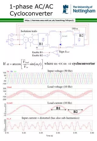
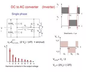
Voltage vg is a sinusoidal input to the basic circuit shown in Figure 1. During the positive half cycle of input voltage, the power flow is controlled by varying the delay angle of the thyristor T1; and thyristor T4 controls the power flow during the negative half cycle. The firing pulses of T1 and T4 are kept 180º (π radians) apart. The waveforms for the input voltage, output voltage and gating signals for T1 and T4 are shown in Figure 2.
If the delay angles of thyristors T1 and T4 are equal the RMS output voltage (Vç) can be found from:
Question • 220 V and 2.2 kW heater is fed by a single phase AC chopper which is connected 220 V AC grid. • Calculate the resistance of the heater • Forα=90, findloadvoltageandpower.
The synchronization signal is obtained via a high-ohmic resistance from the line voltage(voltage V5). A zero voltage detector evaluates the zero passages and transfers them to thesynchronizationregister. • This synchronization register controls a ramp generator, the capacitor which is chargedby a constant current • If the ramp voltage exceeds the control voltage, a signal is processed to the logic. Dependent on the magnitude of thecontrol voltage, the triggering angle α can be shifted within a phase angle of 0° to 180°. • For every half wave, a positive pulse of approx. 30 ms duration appears at the outputs T1 and T4. The pulse duration can be prolonged up to 180°.