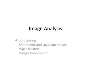
Image analysis
Image analysis. Image algebra. Image Algebra There are two primary categories of algebraic operation applied to images: Arithmetic and Logic. Addition , Subtraction, division and multiplication comprise the arithmetic operation . While AND, OR and NOT make up the logic operation.


Image analysis
E N D
Presentation Transcript
Image analysis Image algebra
Image Algebra • There are two primary categories of algebraic operation applied to images: Arithmetic and Logic. • Addition, Subtraction, division and multiplication comprise the arithmetic operation. • While AND, OR and NOT make up the logic operation. • These operations are performed on two images. • Except for the NOT logic operation, This required only one image, and is done on a pixel –by- pixel basis. • * The Arithmetic Operation • Additionis used to combine the information in two images. Applications include development of image restoration algorithm for molding additive noise, and special effects, such as image morphing in motion pictures.
Subtraction of two images is often used to detect motion, consider the case where nothing has changed in a sense; the image resulting from subtraction of two sequential image is filled with zero-a black image. If something has moved in the scene, subtraction produces a nonzero result at the location of movement. • Applications include Object tracking , Medical imaging, Law enforcement and Military applications • Multiplication and Division are used to adjust(modify) the brightness of an image. One image typically consists of a constant number greater than one. Multiplication of the pixel values by a number grater than one will darken the image (Brightness adjustment is often used as a processing step in image enhancement).
* The Logic Operation The Logic operation AND, OR and NOT form a complete set .meaning that any other logic operation (XOR, NOR, NAND) can be performed by combining of these basic elements. Note they operate in a bit-wise fashion on pixel data. Ex We are performed a logic AND on two images. Two corresponding pixel values are 11110 in one image and 8810 in the second image . The corresponding bit string 11110 =011011112 and 8810=010110002. 011011112 AND 010110002 ------------------ 010010002
The logic operations AND, OR is used to combine the information in two images. This may do for special effects. • But more useful application for image analysis is to perform a mask operation. • Use AND and OR as a simple method to extract Region of interest (ROI)from an image.(this process is called masking). • The Not operator creates a negative of the original image by inverting each bit within each pixel values. • Example: A white square ANDed with an image will allow only the portion of the image coincident with the square to appear in the output image with the background turned black; and a black square ORd with an image will allow only the part of the image corresponding to the black square to appear in the output image but will turn the rest of the image white. • This process is called image masking
• Arithmetic and logical operations may take place on a subset of the image typically neighborhood oriented • Formulated in the context of mask operations (also called template, filter operations,Spatial mask, Kernel , and Window) • Basic concept: let the value of a pixel be a function of its (current) gray level and the gray level of its neighbors (in some sense) Considerthe following subset of pixels in an image Suppose we want to filter the image by replacing the value at Z5 with the average value of the pixels in a 3x3 region centered around Z5 Perform an operation of the form: and assign to z5 the value of z
In the more general form, the operation may look like: This equation is widely used in image processing • Proper selection of coefficients (weights) allows for operations such as – noise reduction – region thinning – edge detection
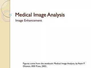
Image Restoration: Image restoration methods are used to improve the appearance of an image by application of a restoration process that use mathematical model for image degradation. Example of the type of degradation: 1. Blurring caused by motion or atmospheric disturbance. 2. Geometrics distortion caused by imperfect lenses. 3. Superimposed interface patterns caused by mechanical systems. Noise from electronic source. Noise Noise is any undesired information that contaminates an image. Noise appears in image from a variety of source. The digital image a acquisition process, which converts an optical image into a continuous electrical signal that is then sampled is the primary process by which noise appears in digital images. What is noise? At every step in the process there are fluctuations caused by natural phenomena that add a random value to exact brightness value for a given pixel. In typical image the noise can be modeled with one of the following distribution: 1. Gaussian (“normal”) distribution. 2. Uniform distribution. 3. Salt _and _pepper distribution.
Spatial filtering is typically done for: Noise Removal using Spatial Filters: Remove various types of noise in digital images. Perform some type of image enhancement. These filters are called spatial filter to distinguish them from frequency domain filter. The Three Types Of Filters Are: Mean filters Median filters (order filter) Enhancement filters Meanadds a “softer” look to an image. Median This median value is used to smoothen the noise with the background. Enhancementhighlight edges and details within the image.
Mean and median filters are used primarily to conceal or remove noise, although they may also be used for special applications. For instance, a mean filter adds “softer” look to an image. The enhancement filter high lights edges and details within the image. • Spatial filters are implemented with convolution masks. Because convolution mask operation provides a result that is weighted sum of the values of a pixel and its neighbors, it is called a linear filter. • Overall effects the convolution mask can be predicated based on the general pattern. • For example: • If the coefficients of the mask sum to one, the average brightness of the image will be retained. • If the coefficients of the mask sum to zero, the average brightness will be lost and will return a dark image. • If the coefficients of the mask are alternatively positive and negative, the mask is a filter that returns edge information only. • If the coefficients of the mask are all positive, it is a filter that will blur the image.
The Mean filters, are essentially averaging filter. They operate on local groups of pixel called neighborhoods and replace the center pixel with an average of the pixels in this neighborhood. This replacement is done with a convolution mask such as the following 3X3 mask. • Note that • the coefficient of this mask sum to one. • the sum of a all are = (1/9+1/9+1/9+1/9+1/9+1/9+1/9+1/9+1/9) =1 • the image brightness will be retained , and the coefficients are all positive . • This type of mean filter smoothsout local variations within an image. • it essentially a low pass filter, • a low filter can be used to attenuate image noise that is composed primarily of high frequencies components.
a. Original image b. Mean filtered image
22 14.2 14.2 14.2 6.7 5 14.2 6.9 7
MEDIAN FILTEER The median filter is a non linear filter (order filter). These filters are based on as specific type of image statistics called order statistics.Typically, these filters operate on small sub image, “Window”, and replace the centre pixel value (similar to the convolution process). Order statistics is a technique that arranges the entire pixel in sequential order, given an NXN window (W) the pixel values can be ordered fromsmallestto the largest. I1≤ I2 ≤ I3...…………………< IN Where IN I1≤ I2 ≤ I3...…………………< INare the intensity values of the subset of pixels in the image.
We first sort the value in order of size (3,3,4,4,5,5,5,6,7) ; then we select the middle value , un this case it is 5. This 5 is then placed in center location. A median filter can use a neighborhood of any size, but 3X3, 5X5 and 7X7 are typical. Note that the output image must be written to a separate image (a buffer); so that the results are not corrupted as this process is performed. (The median filtering operation is performed on an image by applying the sliding window concepts, similar to what is done with convolution). The window is overlaid on the upper left corner of the image, and the median is determined. This value is put into the output image (buffer) corresponding to the centre location of the window. The window is then slide one pixel over, and the process is repeated.
When the end of the row is reached, the window is slide back to the left side of the image and down one row, and the process is repeated. This process continues until the entire image has been processed. Note that the outer rows and columns are not replaced. In practice this is usually not a problem due to the fact that the images are much larger than the masks. And these “wasted” rows and columns are often filled with zeros (or cropped off the image). For example, with 3X3 mask, we lose one outer row and column, a 5X5 mask we lose two rows and columns. This is not visually significant for a typical 256X256 or 512X512 images. The maximum and minimum filters are two order filters that can be used for elimination of salt- and-pepper noise. The maximum filter selects the largest value within an ordered window of pixels values; where as the minimum filter selects the smallest value.
The minimum filters works best for salt- type noise (High value), and the maximum filters work best for pepper-type noise. In a manner similar to the median, minimum and maximum filter, order filter can be defined to select a specific pixel rank within the ordered set. For example we may find for certain type of pepper noise that selecting the second highest values works better than selecting the maximum value. This type of ordered selection is very sensitive to their type of images and their use it is application specific. It should note that, in general a minimum or low rank filter will tend to darken an image and a maximum or high rank filter will tend to brighten an image. The midpoint filter is actually both order and mean filter because it rely on ordering the pixel values , but then calculated by an averaging process. This midpoint filter is the average of the maximum and minimum within the window as follows:
5 5 5 6 3 4 5 3 4 7 The Sorting are :- 3 3 4 4 5 5 6 6 7 5 6 5 5 2 3 3 7 4 The Sorting are :- 2 3 3 4 5 5 5 6 7
3 5 5 3 4 7 1 2 6 The Sorting are :- 1 2 3 3 4 5 5 6 7 5 5 3 4 7 7 2 6 6 The Sorting are :- 2 3 4 5 5 6 6 7 7
Enhancement filter. The enhancement filter conceder here including laplacian typeand difference type. This type is tend to bring out , or enhance, details in the image. The laplacianfilter will enhance will details in all directions equally. the two 3x3 convolution masks for the laplacian type filters are :-
The Differencefilters will enhance details in the directions specific to the mask selected. here are four difference filter convolution masks. corresponding to the line in the vertical,horizontal,diagonal1 and diagonal2 Vertical Horizontal diagonal1 diagonal2
Apply the Laplaci filter mask1 -3-1+ 25- 6- 3 =12 -12-5 +30 -7 -4=2
Apply the Difference filter , main diagonal 2+5-9=-2 3+6-11=-2
Apply the Difference filter horizontal mask 1+5-6=0 0+6-7=-1