Download
1 / 33
350 likes | 638 Vues
Emerging Technology Institute- Summer Workshop Fuel Cell Technology. Day -1: Lecture # 2 Pradip Majumdar Department of Mechanical Engineering Northern Illinois University DeKalb, Illinois 60510. June 21-June 24, 2010. Fuel Cell.

E N D
Emerging Technology Institute- Summer Workshop Fuel Cell Technology Day -1: Lecture # 2 PradipMajumdar Department of Mechanical Engineering Northern Illinois University DeKalb, Illinois 60510 June 21-June 24, 2010
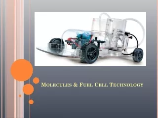
Fuel Cell • The chemical energy contained in a fuel is converted directly into electricity with heat and water as by products. • This is similar to a battery with the difference that the power is produced continuously as long as there is fuel supply.
Attractive Features • High energy conversion efficiency • Improved fuel economy and reduced dependence on conventional fuel • Lower environmentally safe green house gas emission • Modular design • Low noise
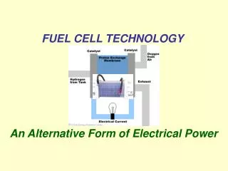
Fuel Cell Operating Principles • A fuel cell consist of two porous electrodes separated by an ion-conducting electrolyte. • A direct hydrogen and oxygen contact and combustion is avoided and replaced by two electrochemical half reactions at two electrode-electrolyte interfaces. • The electrochemical reactions at the anode and cathode sides take place simultaneously producing electricity, and water and heat as the only by-products when hydrogen is used as the fuel. • The free electrons pass through an external circuit, producing power.
Thermodynamic Model Reversible Potential: Gibb’s Free Energy: = -2E-05*(T3) + 0.042*(T2) + 23.313*T – 239015
Performance Characteristics and PolarizationCurve • Major Losses in a Fuel cell: • Activation over-potential • Ohmic losses due to • proton and electron • transport • Mass transport losses • due insufficient gas • supply Fuel Cell Voltage
Fuel Cell Types Fuel cells are classified based on electrolyte type and operating temperature. • Polymer Electrolyte Membrane Fuel Cell (PEMFC) – Solid and Low Temperature type -considered for automobile and small-scale stationary power • Alkali Fuel cell (AFC) and Phosphoric Acid Fuel cell (PAFC) – Liquid electrolyte and for low temperature operation • Molten Carbonate Fuel Cell ( MCFC) and Solid Oxide Fuel cell (SOFC) – Solid and high temperature - Considered for stationary power, hybrid power generation, and cogeneration applications. • PEMFC and AFC are low temperature fuel cell and are considered for mobile and portable applications
Fuel Cell Stacks and System Bi-polar plates MEAs Tri-layer MEA with bi-polar plate Fuel Cell Stack Fuel Cell Power System
Applications • Large scale stationary power generation • Small scale power and heat generation • Propulsive power generation for Transportation vehicle • Auxiliary Power Units (APUs) • Buildings : residential and commercial • Portable applications such as replacement for batteries
Fuel Types • Pure hydrogen - Ideal due to high reactivity and zero emission - Not easily available or produced, store or distribute - Preferred method of production is by water electrolysis, which is currently very expensive - Currently, it is more economical to produce hydrogen from other alternative feed stocks • Natural Gas (Mostly Methane 75-95 % by vol.) - Cheapest and major source of hydrogen • Liquid reformed fuel - octane (ED: 44.4 MJ/kg), diesel (46 MJ/kg) - Need high reforming temperature – 700 C • Bio fuel such as Ethanol (ED: 26.9 MJ/kg), Methanol (ED: 19.9MJ/kg) - need low reforming temperature – 250 C • Gasified solid fuel such as coal or biomass.
Major Challenges For Fuel Cell Commercialization • Improve cell design and efficiency • Increase operating current and power density • Reduce cost (Material and Manufacturing) • Increase reliability and durability of some of the key components such as - Membrane Electrode Assembly (MEA) - Interconnect/ Bipolar Plates - Thermal Heat Management Components - Seals
Simpler fuel processing process - May not need the expensive steam reforming and shift conversion • Allows internal reforming of hydrocarbon fuels to produce hydrogen and carbon monoxide • More tolerant to the presence of impurities in the reactant gases Disadvantages • Higher ohmiclosses • Restrictions on materials for interconnect/Bipolar plates, seals and thermal components
PEMFC Operation Schematic of Tri-layer Fuel Cell Electrochemical Reactions Anode Reaction: Cathode Reaction: Overall reaction:
Applications Vehicle transportation Smaller scale stationary power generation Auxiliary Power Units (APUs) Portable powers for electronics POLYMER ELECTROLYTE MEMBRANE (PEM) Fuel Cell • Attractive Features • Higher power density • Compactness • Lower weight • lower temperature range • Good start-stop • Quicker response to load variations.
Major Technical Issues-PEMFC • Current polymer membrane is limited to operations below 90 C due to the requirement of hydration. • Poor water distribution in the membrane. - leads to drying at anode side and flooding at cathode side. - increase losses at high current density. • Use of expensive catalyst. - need reduced catalyst loading - need alternate less expensive catalyst
Proton Exchange Membrane (PEM) • Major requirements • High ionic conductivity • Lower electronic conductivity • Higher stability and durability • Lower fuel crossover • Higher structural strength • Ease of manufacturability
Polymer Exchange Membrane (PEM) Developed First by General Electric (1962) for Gemini Project. - Polymer solid membrane - Polystyrene Sulfonic acid membrane. - 70 C operating temperature - Needed humidification for water management. - Durability problem.
Polymer Electrolyte Membrane • The purpose of the polymer electrolyte is to transport the proton from anode to cathode side. • Different trade names for polymer membrane (e.g. Nafion) • The polymer membrane such as Nafion is designed to include large amount hydrated regions through which proton can migrate efficiently. • Base material is the Sulfonated Fluoropolymer (Fluoroethylene)
Polymer Electrolyte Membrane The polymer membrane such as Nafion is designed to include large amount hydrated regions through which proton can migrate efficiently. • The mobile liquid – phase is composed of hydrogen ion and water: • Since proton conductivity depends on water concentration in the membrane, it is essential that the membrane is sufficiently hydrated.
Proton Conductivity Proton Conductivity in Nafion-117 increases with water content and temperature and given as σ(λ) = - 0.0051638 + (0.00020217*λ) + (0.0022154*λ2) - (0.0002772*λ3) + (1.4657e-5*λ4) - (2.7746e-7*λ5)
Electrode and Gas Diffusion Layer (GDL) • Reactions at the electrode-membrane interface are surface phenomena, and require large exposed solid surface area. • Electrodes are made in the form porous structures to achieve large surface area. • The pore structure are made of a micro-porous carbon cloth or paper through which reactant gas diffuses towards the interface.
Catalyst • A catalyst layer is added to enhance the electrochemical reaction and reduce activation overpotential. • Small platinum catalyst particles are supported on larger and finely divided carbon Particles. • The reaction regionis characterized by the active surface area where electrode, electrolyte, catalyst are present :
Consumption and Generation • Consumption rates at catalyst-electrode interfaces are specified as follows: Cathode Layer: Anode Layer: Oxygen Gas Hydrogen Gas Water Generation Heat Generation
Inter-connect/Bipolar Plate • Includes separated gas flow channels to supply reactant gasses as well as transfer heat and water to/from electrodes. • The flow field as well as the energy and mass transport in the gas channels effects - gas concentration distribution - current density distribution - mass transport losses. • This is more critical for the operation of the fuel cell at higher current density. MEA Bipolar Plates Tri-layer Membrane Electrode Assembly (MEA) with bipolar plates
Interconnect Or Bi-polar plates • Connects electrically and mechanically the anode of one cell to the cathode of the next. • Material can be ceramic or metallic or graphite or carbon composite. • Plays a key role in the dissipation of heat generated within the fuel cell and in the overall thermal management of fuel cell power system Cooling Channels NIU design for for Fabrication and Test Paten pending
Transport Model Detail components of heat and mass fluxes across the SOFC fuel cell Heat flux Mass flux Membrane Anode Cathode Anode Channel Cathode Channel MEA with bi-polar plate with flow channels
Performance Characteristics and PolarizationCurve • Major Losses in Fuel cell: • Activation over-potential • Ohmic losses due to • proton and electron • transport • Mass transport losses • due insufficient gas • supply at high current • density Fuel Cell Voltage
Activation losses Activation losses are dominant at the low power densities due to the sluggish electro kinematics. The activation losses are directly proportional to the rate of electrochemical reaction. Since cathode overpotential dominates, a simplification of Butler-Volmer equation leads tothe activation losses as
Ohmic Losses • Ohmic losses occur due to the resistance to the ionic flow in the electrolyte, and resistance to the flow of electrons in the electrolyte. • Ohmic losses can be given as
Mass Transfer Losses Mass transfer losses occur at high current densities due to insufficient supply of the gases. At the higher current densities the fuel supply may not sufficient enough to maintain oxygen concentration at electrode catalyst layer at a positive level to sustain the reaction. This is primarily affected by the gas flow field design in terms of pressure drop and mass transfer effectiveness. The mass transfer loss is given by Where = concentration of oxygen at the channel-cathode electrode interface