Download
1 / 32
330 likes | 486 Vues
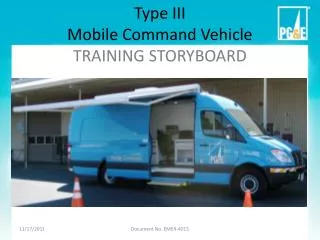
Type III Mobile Command Vehicle TRAINING STORYBOARD. Introduction. The eLearning training will be divided into four parts as listed: Mobilization Support System Communications Center Deployment

E N D
Type IIIMobile Command VehicleTRAINING STORYBOARD Document No. EMER-4015
Introduction The eLearning training will be divided into four parts as listed: • Mobilization • Support System • Communications Center • Deployment The notes section contains the narrator’s script for this slide. The narrator should speak in a calm but authoritative tone.
MobilizationSafety • Transports only two people in cockpit • No personnel in communication center during transport • MCV ground clearance is 10 inches, minimum height clearance is 10 feet 6 inches • MCV has long rear overhang which can impede travel on steep inclines • Obey all speed limits and traffic laws 1/1
MobilizationBefore Leaving • Check fuel • Check generator coolant • Check generator oil • Check supplies on checklist • Secure all contents 1/2
MobilizationStarting Vehicle • Close all doors • Walk around vehicle to make sure all clear • Adjust side mirrors • Fasten seat belt • Start engine • Turn on headlights • Release the parking brake • Place in gear and drive safely 1/3
MobilizationParking • Choose an appropriate parking location • Select location based on the nature of the event, weather and possible evolution of the event. • Consider the safety of personnel who will gather around the command post • Find a relatively level place to park with a maximum of 3” difference from front-to-back, or level the unit • Avoid parking directly under overhead power lines or over gas pipelines • Leave a distance of at least 10 feet on both sides of MCV to allow full use of awning and Cat-5 connecters 1/4
MobilizationParking (continued) • Use a spotter and rear camera • Use spotters, side mirrors, and optionally, the rear camera to back up and reposition MCV in desired location. CAUTION Do NOT rely solely on the rear camera while backing up the MCV. Things may be closer than they appear in the camera view. 1/5
MobilizationParking (continued) • Move the gear shift selector to “P” (park) • Set the parking brake • Turn off headlights • Chock wheels according to incline, decline or flat surface • Set four safety cones, one at each corner of the vehicle 1/6
Support SystemMaster Disconnect Switch • Turn On master disconnect switch • Master disconnect switch disconnects all electrical devices to prevent a drain on the batteries when not in use 2/1
Support SystemAutomatic Step • Deploy Step—Open curb-side door and observe electric step deploy. • Switch step to In/OFF to prevent retracting and redeploying when door closes and opens 2/2
Support SystemGenerator • Start Generator—Depress generator switch for 1 sec. Green light on switch blinks while heating up. Generator will start after 8 secs. Allow generator to warm up for 15-30 secs. 2/3
Support SystemLoad Bank Selector • Turn load bank selector—Turn switch located on driver’s side rear wall to GENERATOR mode 2/4
Support SystemLoad Bank Selector (Optional) • Turn load bank selector—Turn switch located on driver’s side rear wall to SHORE POWER mode 2/5
Support SystemCircuit Breakers • Turn circuit breakers to ON position: MAIN, ACCESSORIES, INVERTER, ACCESSORIES and AIR CONDITIONER. 2/6
Support SystemInverter (Optional) • Confirm inverter status—The inverter is turned on by the circuit breaker in the previous step. Check the job aid on rear door to verify status. 2/7
Support SystemHVAC • Turn on HVAC—Allow generator to stabilize, then turn on roof-mounted heating or air conditioning (HVAC) system to low setting. • After 15-20 seconds, turn HVAC thermostat and fan speed to desired setting. 2/8
Support SystemAwning (Optional) The MCV is equipped with an awning to provide shade on the curb side of the vehicle. • Deploy awning by activating switch located adjacent to the sliding door • OUT – Press and hold for 3 seconds to extend awning • STOP – Press to stop awning at any desired position • IN – Press and hold for 3 seconds to retract awning • If awning does not deploy or retract by pressing awning buttons, use the stow arm stored in rear compartment 2/9
Support SystemScene Lighting (Optional) • For added vehicle and surrounding visibility, MCV is equipped with four scene lights, two on each side of the vehicle. • Do NOT use these lights while vehicle is in motion. • Locate scene light switch to the left of the steering column. • Press LEFT SCENE or RIGHT SCENE or both. 2/10
Communications CenterOn-Board Equipment • Type III MCVs are equipped with the following: • 3 Cisco IP telephones • 3 HP LCD monitors • 2 Dell laptops with docking stations, keyboards and mice • Dell desktop computer with wireless keyboard and mouse • HP Officejet Pro printer/scanner • HP Plotter • LG flat-screen color TV with remote • Satellite phone • Wireless Access Point (WAP) • CAT-5 patch panel 3/2
Communications CenterOn-Board Equipment (continued) • Type III MCVs are equipped with the following: • Kenwood TK790 150 MHz legacy radio • Kenwood TK890 450 MHz legacy radio • Tait TM8200 450 MHz trunked radio • ACU-2000IP radio-to-radio controller 3/3
Communications CenterPhones & Data • Turn on phones and data • Switch on red rocker switches in the IT rack • It may take 2 minutes for the phones and Wi-Fi to self-boot • Press GFI switches below phones to turn on power strip. Amber light is off, no light is on. • Once the phone number list displays, the connection is ready 3/4
Communications CenterTelevision • Turn on television • Check for green light on wall box to ensure open air TV antenna is on. • Turn on LCD TV using the remote and tune to local TV broadcast as desired.3/5
Communications CenterComputers • There is one desktop and two laptops onboard • The desktop computer controls the plotter • All MCV computers require an RSA token and PIN for VPN access to the PG&E network. There are no guest tokens available. • Due to installed security software and the EVDO network, it may take five minutes for the boot process to complete 3/6
Communications CenterSoftware • Computers have all necessary emergency response software installed. See EMER-4013 for a summary of available software. 3/7
Communications CenterWireless Access Point (WAP) The WAP enables PG&E employees who bring their own PG&E computer to the scene to connect wirelessly to the network. • To use the WAP: • Click the wireless icon in the task bar. • Select Enable Radio from menu, if not already selected 3/8
Communications CenterWAP(continued) • Double-click correct MV SSID, which is the vehicle number prepended with a ‘B’ • Enter password that corresponds to the selected SSID. Password is vehicle number two times preceded by lowercase ‘b’. Example: MV SSID = B26036 Password = b26036b26036 • For network authentication, check box for WPA-Personal (PSK) with AES. 3/9
Communications CenterRadios The Sprinter MCV is equipped with the following two-way radios and channel control computer, which networks disparate radios: • Kenwood TK790 – A 150 MHz legacy radio. • Kenwood TK890 – A 450 MHz legacy radio. • Tait TM8200 – A 450 MHz trunked radio. • ACU-2000IP – Controller Refer to procedure EMER-4013 and radio job aids in vehicles for usage information. 3/10
DeploymentMaintenance • Transportation Services is responsible for servicing the vehicles per the fleet maintenance schedule. • Sprinters will be plugged into a garage LAN connection on a regular basis to allow for automatic software updates to the on-board computers. • All other maintenance issues will be resolved as necessary. 4/1
DeploymentStorage The Type III MCV’s home base are as follows: 4/2
DeploymentActivation Standard activation process: • EOC Commander activates MCVs. • Contact the EOC On-call Coordinator at 415-973-9999 to request authorization. • Onlytwo Type IIIMCVs can be deployed at a time for a non-emergency event. • EOC Commander canrecall MCVs if needed for emergency use. • Transportation Services tracks MCV use so location is known at all times. • Transportation Services is the only entity authorized to drive the vehicles and handles set-up and take-down. 4/3
Questions? 4/4