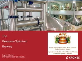
The Resource-Optimized Brewery
The Resource-Optimized Brewery. Stephen O‘Sullivan KRONES PROCESS TECHNOLOGY. Lowering consumption More efficient equipment and technology in beer production Energy recovery systems Improved system design Utilization of waste materials Waste water recycling Utilization of spent grains

The Resource-Optimized Brewery
E N D
Presentation Transcript
The Resource-Optimized Brewery Stephen O‘Sullivan KRONES PROCESS TECHNOLOGY
Lowering consumption More efficient equipment and technology in beer production Energy recovery systems Improved system design Utilization of waste materials Waste water recycling Utilization of spent grains Alternative Energy Sources Wind or solar energy Biomass Hydropower Three pillars of sustainability
The demand for fossil fuels is growing with increasing global population and growth in consumption. • In spite of falling new oil discoveries, demand for oil continues to grow all the time. • Since 1985 the volume of oil consumption has outstripped new discoveries. • Oil Production is becoming increasingly difficult, so the price of oil & natural gas will increase even more over the long term. • Extract yield used to be the critical cost factor for a brewery in the past, in future it will be the Cost of Energy. New discoveries of oil and oil production (1920-2004) Second largest oilfield (Kuwait) World's largest oilfield (Ghawar S.A.) 1. Oil crisis new discoveries 2. Oil crisis oil production Deep sea exploration Source: ASPO – Association for the study of the Peak Oil & Gas
The Overall brew house yield (OBY) of modern brewhouse systems are already at 98 - 99%. • We’ve practically reached the limit of what is technically possible for increasing OBY. • Capital investment aimed at increasing the yield any further achieves a lower Return on Investment • Investment geared towards cutting energy consumption becomes more the more practical option • Consumers also expect that their brewery utilizes sustainable production systems.
Source: Katechismus der Brauereipraxis; J. Dworsky, K. Lense; (1926) Energy Recovery in the Brewhouse Typical Recovery Sources • Kettle vapour condenser • Condensate cooler • Wort cooler Typical Applications • Lauter-wort heating • Heat for mashing water • Heat for sparging water • Heat for cleaning / CIP
Steam Steam Cooling/Water Steam Steam Primary Mashing-in Mashing Cooling Lautering Heating-up 2 Boiling CIP brewhouse Heating-up 1 Secondary Hot water Energy storage unit Hot water Hot water Hot water Energy flow in the traditional brew house (with traditional Wort kettle Energy Recovery)
Traditional brew house with wort kettle Energy Recovery • Mill • Mash Tun • Lauter Tun • Pre-Run Vessel • Energy Storage Tank • Vapor Condenser • Lauter Wort Heater • Wort Kettle • Whirlpool • Wort Chiller
Steam Steam Steam Cooling/Water Steam Primary Mashing-in Mashing Cooling 2 Lautering Heating-up 2 Boiling Cooling 1 CIP brewhouse Heating-up 1 Secondary Hot water Energy storage Hot water Hot water Hot water Energy storage Hot water Energy flow with EQUITHERM
EquiTherm - Equipment and technology • Using the first stage in the wort chiller to recover hot water at 96°C (200F) and store in an energy storage tank. • This acquired energy is enough for the mashing process depending on temperature of the mash • Usable water temperature is adjusted by mixing water from upper (96°C) and lower (76°C) (205-167F) strata of the energy storage tank. • The return hot water is fed into the energy storage tank in temperature strata. • Radiation losses and start-up energy are regulated and compensated by the CIP heat exchanger. The first brew house with EquiTherm: Bergquell Brewery Löbau, 2010
Mash Tun Design – Using Recovered Energy • The mash is heated up with energy obtained from the first stage of the wort cooler. • Retrofit Existing Mash Tun - Jacket would require separate hot water and steam sections • Compared to steam, difference in temperature between heating medium and the mash is relatively low. • Use of pillow plates enables heat transfer rates of 1 K/min based on appropriate jacket dimensioning. • Flow of hot water to the heating surfaces. fed from the top to the bottom through the pillow plates, creating the effect of a counter flow heat exchanger.
Heat flow Heat transfer coefficient Temperature difference (Heating) surface Mash Tun Design - Equipment and technology of EquiTherm • ShakesBeer EquiTherm • The turbulent flow pattern of the mash on the heating surface improves the heat transfer coefficient and with this, the heating rate • This is the only way of ensuring that the heating surface is large enough in spite of the reduced temperature difference
Equipment and technology • Energy Storage Tank Design • One Storage Tank can be used jointly by both the EquiTherm and lauter wort heater & vapor condenser • Given the different retuning hot water temperatures a solution is required to avoid mixing zones in the tank • A stratified charging pipe enables the water to attain a level in the tank according to density/temperature without much mixing
Figures, data and facts Steam capacity • Peak loads for the steam boiler system • With more than eight brews per day production, the heating up involved in the mashing process and the boiling of the wort inevitably run parallel to each other. • The steam boiler system must be designed for the maximum possible peak load. • With the energy required for the mashing process being supplied by EquiTherm, the peak is reduced by this amount. Steam capacity
Figures, data and facts • Savings with EquiTherm “Standard” brewhouse assumes Energy recovery from Wort Boiling already in place
Vibration Transponder Technology in Mash Tun • Faster Mash Conversion • Possible additional brew/day • Dimpled Surface Jacket • Improved Heat Transfer • Reduced fouling • Less CIP & Rinse Water Consumption • Optimized deaeration • Quality
Effect of Wort Heating and Boiling on Total Energy Demand • Wort boiling represents one of the greatest individual energy consumers in a brewery. • State of the art brewery - wort boiling can represent up to 30% of the total heat demand. → Large savings potential available
During the wort boiling process the free DMS must be expelled to such an extent that the taste threshold value of 100 ppb will not be exceeded during the re-increase in the whirlpool High temperatures separate more DMS precursor, but free DMS is no longer reduced because there is no movement / circulation The content of free DMS remains constant in the cooled wort. free DMS Whirlpool Boiling Cooling 100 ppb Standard Time Energy
The boiling process is divided into three phases: • Phase 1: Natural circulation by energy supply and pump circulation Natural circulation Pump circulation Equipment and Technology of STROMBOLI • The Stromboli boil system has two circulation circuits: the natural circulation of the boiler and the pump circulation. • Phase 2: Pump circulation with reduced energy supply • Phase 3: Natural circulation by energy supply and pump circulation • The circulation of the wort can be separated from the total evaporation. With the variation in the pump speed and phase duration new parameters are available to control the boiling process.
Stromboli wort boiling process Stromboli allows the circulation of the wort to be separated from the evaporation In phase 2 of the boiling process the wort is circulated with an external pump and the Venturi nozzle only The Stromboli wort boiling process therefore allows a reduction in the free DMS content with reduced energy input free DMS Whirlpool Boiling Cooling 100 ppb Phase 1 Phase 2 Phase 3 Stromboli Standard Time Energy
Venturi effect as key to success • The core of the Stromboli internal boiler is a Venturi nozzle installed above the pipe bundle. • Driven by an external pump, the wort is conveyed via the central ascending pipe. This creates a vacuum on the outside of the nozzle which supports the flow of wort in the pipe bundle. • At a circulation rate with the 8-fold amount of wort to be boiled per hour, almost the same circulation rate is also generated by the Venturi nozzle. • System design means 4 m/s is the maximum speed for the wort flow. Up to 30 Brews between CIPs
Wort quality Wort has valuable substances but also some undesired components If certain levels of these components are exceeded then a loss in quality will result Wort stripping offers the abilty to remove undesired flavors from wort in a controlled way Energy saving Not only will quality improve, wort stripping also provides the possibility to reduce total evaporation and energy consumption during wort boiling step Wort Stripping • Stripping is a technology combining classical quality with modern brewing processes
Stripping enables a reduction of free DMS content below threshold even if boiling time is reduced from 60 to 40 minutes Wort stripping can be used for: reducing the boiling time, i.e. saving energy, with constant wort quality or reducing the percentage of free DMS with constant boiling time With this, wort stripping allows constant boiling processes with different raw material qualities DMS - Indicator for the wort quality Frees DMS* 60 minutes boiling time 40 minutes boiling time + stripping 100 µg/l Whirlpool Boiling Cooling * Simplified display as linear function time • Wort stripping allows the reduction of free DMS straight before wort cooling
Equipment and Technology - Boreas • Spin injector • Wort is set into rotation via the spin injector. Using the appropriate speed and angle, the wort is applied continuously already in the cover and a turbulent falling film runs down on the container wall. • The change of velocity at the outlet of the spin injector leads to a pressure drop in the wort layer, which supports the stripping effect. • The expelled free DMS is led to atmosphere through the inner space of the spin injector. • The product path can be used for cleaning agents, no further installations are required.
The total pressure in the stripping vessel is based on the partial pressures of the individual phases (shown here in a simplified way as H2O and free DMS) Depending on the temperature there will be a balance between steam and free DMS in the gas phase. This will be proportional to the percentage of distribution between the individual partial pressures. Until the point of saturation there will be a constant evaporation of water and free DMS Partial pressure as key to success 1000 vessel pressure 95° = 150 mbar DMS + 850 mbar H2O Wort H2O Free DMS
The evaporation of DMS is proportional to the creation of vapor during turbulent wort flow within the stripping vessel Evaporation enthalpy means the intensity of the generation of water vapour happens proportionally to the temperature difference between the wort inlet and outlet In the gas “zone” of the stripping vessel a balance point between vapor and free DMS is created. By the injection of strip gas the saturated gas is displaced continuously Strip gas keeps the driving concentration gradient between wort film and gas zone at a constant level, so that the reproduction of water vapor and with this, the reduction of free DMS can be controlled Partial pressure as key to success Wort inlet Wort outlet Strip gas (CO2, N2, air) Water steam and free DMS Strip gas, water steam and free DMS
Reduction of undesired aroma components 100 90 80 70 60 50 Reduction % 40 30 20 10 0 DMS Heptanal 2 Methylbutanal Wort color as indicator for oxidation 10 9,5 9 8,5 8 7,5 Colour EBC 7 6,5 6 5,5 5 Without stripping CO2 stripping Air stripping Wort analysis • Depending on the amount of strip gas and the temperature difference between the inlet and the outlet, the DMS reduction can be up to 70 % • In the same way, other unwanted aromatic substances can be removed • The usage of air as strip gas causes no oxidation of the wort • The partial pressure creates a steam layer at the wort surface which avoids contact between wort and oxygen
Conventional brewery (12 brews/d, 500 hl, 11°P) 17°P → 11°P → 11°P → 11°P → 1.42 m hl VB Process concept: High-Gravity Brewing Brew size 500hl (Absolute blending factor : 1,0) High-Gravity Brewery (12 brews/d, 275 hl, 20°P) Brew size 275hl -45% 24°P → 20°P → 17°P → 11°P → 1.42 m hl VB First dilution: 1.18) (Second dilution: 1.55) (Absolute blending factor : 1.82)
Savings potential by high gravity in the brewhouse 500 hl cast out with 11°P compares with 275 hl with 20°P Calculation basis: Krones standard brewhouse; 8°C cold water temperature; 80° hot water temperature; 0.09 €/kWh (thermal); 0.12 €/kWh (electric); 0.10 €/hl fresh water → Total savings potential: up to € 400,000 per year → Total savings potential in investment costs: up to € 450,000 Additionally large potential in the cold area (tank, line and filter size; cooling energy, compressed air, …)
Reduction in CIP expenditure based on Visual Scanning Technology • Integration of the TopScan in the CIP process • Dynamic cleaning process depending on the degree of dirt contamination • “As little as possible but as much as necessary” • Reduction in the rinsing water consumption • Reduction in the cleaning agents • Time saving • Increased plant efficiency before the CIP (contamination marked) After a CIP time of 10 min.
Pipe system concept • Decentralised piping design • The short connection between the two valve blocks allows for savings to pipes, valves, cleaning media and displacement water (TWIN-PRO) • Linear piping design • All pipes must be guided past all tanks. The amount of extra cost and work exponentially increases with each additional tank
Intelligient Pipe Fence Design in the Cellar – Twin Pro • Pipe system concept • One valve block each for the filling and draining processes in the tank loop • Connection of up to four tanks to one ring channel which in turn is connected to the main lines via double seat valves • Required number of pipes and valves reduced by up to 30% • Required volume of water for displacement and cleaning agents reduced by up to 35% due to minimized pipe lengths
Produce the best quality • Protect the environment • Conserve resources Sustainable thinkingThanks !