Download
1 / 64
640 likes | 839 Vues
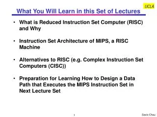
What You Will Learn in this Set of Lectures. What is Reduced Instruction Set Computer (RISC) and Why Instruction Set Architecture of MIPS, a RISC Machine Alternatives to RISC (e.g. Complex Instruction Set Computers (CISC))

E N D
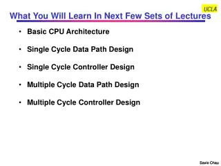
What You Will Learn in this Set of Lectures • What is Reduced Instruction Set Computer (RISC) and Why • Instruction Set Architecture of MIPS, a RISC Machine • Alternatives to RISC (e.g. Complex Instruction Set Computers (CISC)) • Preparation for Learning How to Design a Data Path that Executes the MIPS Instruction Set in Next Lecture Set
350 300 RISC 250 200 Performance 150 Intel x86 100 RISC introduction 50 0 1982 1984 1986 1988 1990 1992 1994 Year What is RISC and Why? • RISC is an architecture design concept based on the principle that simpler hardware runs faster (e.g. MIPS). It uses smaller and regular instruction set to achieve performance, while relying on compiler technology to achieve functions used to done by complex instructions. • Opposite to RISC is Complex Instruction Set Computer (CISC) (e.g. Intel x86). CISC believes complex instructions implemented in hardware can achieve higher performance. Language directed architecture such as Burroughs’ B5500 (Algol) or B4500 (Cobol) are extreme cases. Courtesy D. Patterson
The MIPS Instruction Set MIPS is a Reduced Instruction Set Computer (RISC), Characterized By: • It is a Load- Store Machine: Computation Is Done On Data In Registers i. e., Operands of Arithmetic And Logical Operations Do Not ResideIn Memory. Data Is Moved Between Memory And Registers Before Being Used and Back To Memory After Computation Is Finished By Load and Store Instructions • A Relatively Small Number Of Instructions and Data Types • All Instructions Are Of The Same Length • There Are A Very Small Number Of Instruction Formats (3) • There Are A Small Number Of Addressing Modes - Three For Accessing Operands (Register- Direct, Based, Immediate) and One For Computing Jump Addresses (PC- Relative) Courtesy M. Louie
How to Design an Instruction Set Architecture • Four things need to be considered • What operations will be performed by this instruction set? • Op code • What kind of data this instruction set will operate on? • Data type • Where can you find the data? • Memory and register architecture • How to access those data? • Address modes • Four design principles (that lead to reduced instruction set architectures) • Simplicity favors regularity • Smaller is faster • Good design demands good compromises • Make the common case fast
What Operations Performed by MIPS ISA? • Basic Functions • Arithmetic and Logic Operations • Need 2 source data and 1 destination to store result • Data transfer to and from the memory • Load a data from a memory address (+ offset) and put it in a register • Store a data in a register into a memory address (+ offset) • Conditional branches • Need a way to determine a condition • Need a target memory address to branch to if condition is met (or not met), go to next instruction otherwise • Jump and subroutine linkage (procedure call) • Need a large range of target memory address to branch • Procedure call needs a return address • Additional functions: Examples • Move data between registers, to I/O, or to co-processor • Exception and Interrupt Instructions
What Datawill be Operated on by MIPS ISA? • Data Types • Signed: Numbers that can be either positive or negative • Integers • Floating Point Numbers • Relative Address • Unsigned: just positive • Absolute Address • Data Sizes • Word (32 bits) • Half-word (16 bits) • Byte (8 bits)
Where the MIPS ISA Stores Data? • In Registers — used by R-Type instructions) • Within the instruction — used by I-Type instructions • In Memory — always transferred to/from a register by a load/store (also I-Type) instruction first • The memory address is in a register • The memory address in a constant in the instruction • The memory address is sum of a register and a constant in the instruction • The memory address is relative to the PC (i.e., sum of the PC and a constant in the instruction)
MIPS R2000 / R3000 Programmable Storage • Memory: • 232 Addresses (32-bit Address) • 230 Memory Words; 1 Word = 4 Bytes • Byte Addressable • Registers: • 31 32-Bit General Purpose Registers R1 - R31 General Purpose Register 0 = Constant Value 0 Note: The indicated register usage is by convention only, not restricted by the MIPS architecture
MIPS R2000 / R3000 Programmable Storage • Registers (Continued) • 32 Floating Point Registers (F0-F31) • Double Precision = 16 FP Register Pairs • Single Precision = 16 FP Registers (Even Addresses) • Other Registers • PC = Program Counter Register • HI and LO: for 64- Bit Integer Arithmetic Results • (Multiplication) HI, LO = 64- Bit Integer Product • (Division) LO= Quotient, HI= Remainder • Exception Registers • EPC (Execption Program Counter): Address of instruction causing exception • Cause: Exception type and pending interrupt bits • BadVaddr (Bad Value Address): Address of data causing exceptions • Status: Interrupt mask and enable bits
How Does MIPS ISA Access the Data? Register (Direct) E.g., add $1, $2, $3 $1$2+$3 OP RS=$2 RT=$3 RD=$1 Register Immediate E.g., addi $1, $2, 100 $1$2 +100 OP RS RT Immediate=100 Base + Index E.g., lw $1, 100($2) $1Mem[$2+100] OP RS=$2 RT Immediate=100 Register Memory PC-Relative E.g., bne $1, $2, 100 Goto Mem[PC+100] if $1=$2 OP RS RT Immediate = 100 PC Memory Psuedo-Direct E.g., J 1000 Goto Mem[PC(31:30):1000] OP Address = 1000 PC Memory
The Most Basic Four MIPS Instructions You will learn other instructions later. See backup slides at the end of this presentation for more MIPS instructions See backup slides at the end of this set of presentation for more MIPS instructions
MIPS Instruction Formats R- Type Instructions General Format: op RD, RS, RT Meaning: RD RS op RT Example: add $1,$2,$3 Meaning: $1 $2 + $3 Machine Code Format of the Instuction: • The Meaning of Each Name of The Fields in MIPS Instructions: • OP: Operation of Instruction • RS: The First Register Source Operand • RT: The Second Register Source Operand • RD: The Destination Register Operand; It Gets The Result of the Operation • SHAMT: Shift Amount for shift left logical or shift right logical instructions • Funct (Function Field): Selects the Variant of the Operation in the OP Field Example: the OP field for all R-Type instructions is 0, but Funct field for add is 3210 (1000002), subtract is 3410 (1000102), and is 3610 (1001002), etc. See text pp. A-55 to A-75 for more formats of MIPS instructions
OP RS RT Immediate 6 Bits 5 Bits 5 Bits 16 Bits MIPS Instruction Formats I- Type Instructions General Format: op RT, RS, Const Meaning: RT RS op Const Example: addi $1,$2,100Meaning: $1 $2 + 100 Alternative Format: sw $1, 100($2) Meaning: $1 Mem[$2+100] Machine Code Format of the Instuction: • Meaning of Each Name of The Fields in MIPS Instructions: • OP: Operation of Instruction (including information about the instruction type) • RS: The First Register Source Operand • RT: The Destination Register Operand; It Gets The Result of the Operation • Immediate: Constant • Applications of I-Type Instructions • Immediate Addressing Format (e.g., addi, ori, andi. Immediate = constant) • Data Transfer Instructions (e.g., lw, sw. Immediate = address) • Conditional Branch (e.g. beq, bne. Immediate = displacement from PC) See text pp. A-55 to A-75 for more formats of MIPS instructions
MIPS Machine Language See text page 153 for more machine encoding of MIPS instructions
Assembly and Machine Language Example Register is assigned by compiler, which usually follows MIPS convention A[ i] = h + A[ i]; is compiled into: lw $8, Astart($ 19) # Temporary reg $8 gets A[ i], Astart is a const. add $8,$ 18,$ 8 # Temporary reg $8 gets h + A[ i] sw $8, Astart($ 19) # Stores h + A[ i] back into A[ i], Astart is a const. How to select registers? Machine Code (in decimal value) lw add sw Machine Code (in binary value) lw add sw
Multily and Divide Instructions(Psuedo-Instructions) Psuedo-Instructions are commonly used instructions that are not directly implemented in hardware but translated into one or more of the basic set of instructions • Multiply, Divide • MULT rs, rt # Multiply • MULTU rs, rt # Unsigned Multiply • DIV rs, rt # Divide • DIVU rs, rt # Unsigned Divide • Move Result From Multiply, Divide • MFHI rd # Move Hi reg to RD • MFLO rd # Move Lo reg to RD • Move To HI or LO • MTHI rd • MTLO rd Multiply instruction is accomplished by a series of shift and add instructions and the results are accumulated in the HI and LO registers
Adding Conditional Branch & Jump Instructions See backup slides at the end of this presentation for more MIPS instructions Question: What is $31? Answer: By MIPS convention, $31 is the return address register after procedure call
bne $t0 $s1 1000 MIPS Instruction Formats J - Type Instructions (e.g., j 10000) OP Address 6 Bits 26 Bits • J-Type Instructions uses pseudodirct addressing, where the jump address is the 26 lower bits (i.e., the address bits) of the instruction, left shifted by 2 bits (i.e., word addressable only), and then concatenated with the upper 4 bits of the PC OP Address Memory Address 0 0 Program Counter unchange PC[31:28] (PC[27:0]+4) replaced by Address4 What about branch instructions? Ans: Branch instruction is an I-type instruction using PC-relative addressing Example: Memory If $t0 $s1, then New PC = Old PC + 4 + 41000 0 0 Program Counter
Branches/Jump Machine Language • Branches: • The target address is in PC: PC PC + 4 + (16-bit Address Field)* 4 • Jumps: • The target address = instruction bits 25:0 concatenate with PC bits 31:26 L=20 L=20 L=25
A Coding Example with Conditional Branches Example: • In the following C code segment, f, g, h, i, and j are variables: if (i == j) goto L1; f = g + h; L1: f = f - i; • Assuming the 5 variables correspond to 5 registers $16 through $20 i.e. f in $16; g in $17; h in $18; i in $19; j in $20 what is the compiled MIPS code? Answer: • The Compiled Program (Assembly Code) is: beq $19,$20, L1 # goto L1 if i equals j add $16,$17,$18 # f = g + h L1: sub $16,$ 16,$19 # f = f - i What would the machine code look like for this?
Another C Compilation Example with Loops • C Code: Loop: g = g + A[i]; i = i+ j; if (i != h) goto Loop; Assuming the Following Register Assignments f in $16; g in $17; h in $18; i in $19; j in $20; and a constant 4 in $10 A[i] is an array in memory with starting address at Aaddr[0] • Assembly Code: Loop: mult $19,$10 # (HI, LO) regs = i * 4 mflo $9 # reg $9 least sig. 32 product bits lw $8, Aaddr($9) # Temporary reg $8 = A[i*4] add $17,$17,$8 # g = g + A[ i] add $19,$19,$20 # i = i + j bne $19,$ 18, Loop # goto Loop if i != h Need to compute BYTE address from i, which is word address (1 word = 4 bytes) Why do this?
L0 L1 e.g., k=2 L2 L3 An Example Using a Case Statement Register Assignments: f in $16; g in $17; h in $18; i in $19; j in $20; k in $21 Constant 4 in $10 • C Code: switch (k) { case 0: f = i + j; break; case 1: f = g + h; break; case 2: f = g - h; break; case 3; f = i - j; break; } The following MIPS assembly language will work, provided four words in memory, starting at location JumpTable, have addresses corresponding to the labels L0, L1,L2, and L3 respectively. Since we are using the variable k to index into this array of words, we must first multiply by 4 to turn k into its byte address equivalent.. Switch: mult $10, $ 21 # (HI, LO) regs = k * 4 mflo $9 # Temp reg $9 = least sig. 32 bits of product lw $8, JumpTable($ 9) # Temp reg $8 = Jumptable[k] jr $8 # Jump based on register $8 L0: add $16,$ 19,$ 20 # k= 0 so f gets i+ j j Exit L1: add $16,$ 17,$ 18 # k= 1 so f gets g+ h j Exit L2: sub $16,$ 17,$ 18 # k= 2 so f gets g- h j Exit L3: sub $16,$ 19,$ 20 # k= 3 so f gets i- j Exit: Word Addr Byte Addr Memory JumpTable 0 0 1 4 2 8 3 12 L2 Reg $8
Procedure Calls • Procedure call is used by programmers to structure programs, for easier to understand and reusuability. Example: main() /* This is the calling procedure (caller) */ { funct(100); /* procedure call */ } int funct(arg) /* This is the called procedure (callee) */ { … } • In order to execute procedure call • The calling procedure (caller) has to put parameters in a place where procedure can access • The calling procedure (caller) has transfer control to the called procedure while saving the return address at the same time • The called procedure (callee) has to put return value in a place where the calling program can access • The called procedure (callee) has return control to the calling program at the point of origin
MIPS Software Convention for Registers • 0 zeroconstant 0 • 1 atreserved for assembler • 2 v0 expression evaluation & • 3 v1 function results (return value) • 4 a0arguments • 5 a1 (calling procedure uses these • 6 a2 registers to pass arguments • 7 a3to the called procedure) • 8 t0 temporary: caller saves • do not need to be preserved across procedure calls • . . . (called procedure can clobber) • 15 t7 • 16 s0 callee saves • need to be preserved across procedure calls • . . . (calling procedure can clobber) • 23 s7 • 24 t8 temporary (cont’d) • 25 t9 • 26 k0reserved for OS kernel • 27 k1 • 28 gp Pointer to global area • holding a program’s static data • 29 sp Stack pointer • 30 fp frame pointer • 31 raReturn Address (HW) • Stack frame -- A block of memory allocated on the stack for the subroutine call environment. • Purpose: • hold values passed as subroutine arguments • save register values that the calling subroutine needs to use after the callee returns • provide space for local variables since there are only a limited number of registers
An Overly Simplified Example Addr main() /* Caller */ { x = y + z; funct(arg); /* procedure call */ … } $v0 w ($2) 1 arg $a0 ($4) 2 funct addr 1 2 main addr main addr 3 1 2 3 PC 3 x w $t0 ($8) 3 y v $t1 ($9) main addr3 $ra ($31) z $t2 ($10) Addr int funct( arg ) /* Callee */ { w = arg – v; return (w); } arg 1 2 3 • But! • What if there are more than 4 arguments? • What if there are some register values need to be preserved across procedure call (e.g., if you want to preserve the value x)? • What if another procedure call happens before the current procedure is completed?
Call-Return Linkage: Stack Frames • Solution: • Save the needed information (e.g., arguments, return address) onto a stack in memory • Information needed by the called procedure are grouped into a stack frame • Many variations on stacks possible (up/down, last pushed / next ) High Mem Reference Arguments and Local Variables at Fixed (negative) Offset From FP FP ARGS (frame pointer points to 1st word of frame) Callee Save Registers (old $fp, $ra, $s0,etc) Stack Frame or Activation Record Local Variables SP (stack pointer points to last word of frame) Grows and shrinks during expression evaluation Low Mem
FP PC SP PC FP FP SP PC PC SP PC FP SP SP FP Nested Procedure Call Using Stack Frames main() { … funct1(arg0 … argN); … } Stack frame of caller of main arg4 … argN for funct1 (pushed by main) Return address to main (pushed by funct1) main’s saved register $s0 … $s7, $fp (pushed by funct1) funct1(arg0 … argN) { … funct2(arg0 … argM); return(w); } Other local variables needed by funct1 (pushed by funct1) arg4 … argM for funct2 (pushed by funct1) Return address to funct1 (pushed by funct2) funct1(arg0 … argM) { … y = x + z; return(y); } funct1’s saved register $s0 … $s7, $fp (pushed by funct2) Other local variables needed by funct2 (pushed by funct2)
PC SP FP PC PC FP SP FP SP Return From Nested Procedure Call main() { … funct1(arg0 … argN); … } Stack frame for main arg4 … argN for funct1 (popped by funct1 and trashed) Return address to main (popped by funct1 and put back to $ra) main’s saved register $s0 … $s7, $fp (popped by funct1 and put back to $s’s) funct1(arg0 … argN) { … funct2(arg0 … argM); return(w); } Other local variables needed by funct1 (popped by funct1 and trashed) arg4 … argM for funct2 (popped by funct2 and trashed) Return address to funct1 (popped by funct2 and put back to $ra) funct2(arg0 … argM) { … y = x + z; return(y); } funct1’s saved register $s0 … $s7, $fp (popped by funct2 and put back to $s’s) Other local variables needed by funct2 (popped by funct2 and trashed)
MIPS Instructions for Procedure Call • MIPS uses a jump and link instruction for procedure calls • Jumps to the address specified in the lower 26 bits of the instruction • Simultaneously save the address of next instruction (i.e. PC+ 4) in the Return Address (RA) register (R31)
MIPS Procedure Call: Put Everything Together • Step 1: Before the caller makes the subroutine call, the caller: • 1.1 Pushes onto the stack those values in caller-saved registers ($t regs) that the caller wants to use after the callee returns • 1.2 Stores subroutine call arguments in registers 4-7 ($a regs) and pushes any remaining arguments onto the stack for the callee stack frame • Step 2: When the subroutine is invoked, the callee then: • 2.1 Allocates memory on the stack for its stack frame • 2.2 Saves environment registers (e.g., return addr.($31), old frame pointer($30)) and callee-saved registers ($s regs) onto the stack so that the callee can alter them and then restore them before returning (Note: Need to store the $a and $s registers before they are modified) • 2.3 Updates the frame pointer ($fp) to point to the callee stack frame • Step 3: Just before the callee returns, the callee: • 3.1 Puts return values in registers 2-3 ($v regs) • 3.2 Restores registers saved in Step 2.2 (above) and pops the stack frame
Procedure Call Coding Example main: ... 104 addi $a0, $0, 10 # save arg1 to $a0 108 addi $a1, $0, 11 # save arg2 to $a1 112 addi $a2, $0, 12 # save arg3 to $a2 116 addi $a3, $0, 13 # save arg4 to $a3 120 addi $t0, $0, 14 # save arg5 to $t0 124 sw $t0, 0($sp) # save (not push) arg5 to stack 128 jal funct1 # jump to called procedure 132 … funct1: 500 subu $sp, $sp, 32 # allocate 32 bytes to new frame 504 sw $ra, 20($sp) # save return address to main 508 sw $fp, 16($sp) # save old frame pointer 512 addi $fp, $sp, 32 # new frame pointer = old sp 516 add $v0, $0, $0 # initialize w 520 add $v0, $v0, $a0 # calculate w from arguments 524 add $v0, $v0, $a1 528 add $v0, $v0, $a2 532 add $v0, $v0, $a3 536 lw $t0, 0($fp) # retrieve the 5th argument 540 add $v0, $v0, $t0 # add to w (already in $v0) 544 lw $ra, 20($sp) # pop return address to $ra 548 lw $fp, 16($sp) # pop old frame pointer 552 addi $sp, $sp, 32 # pop stack 556 jr $ra # jump back to main main() { … funct1(10,11,12,13,14); … } funct1(arg1 … arg5) { w = arg1 + arg2 + arg3 + arg4 + arg5; return(w); } Register Assignments: $a0 … $a4: arguments $fp: frame pointer $sp: stack pointer $v0: return value $ra: return address $t0: temporary register
10 11 12 13 Procedure Call Coding Example (Animated) main() { … funct1(10,11,12,13,14); … } 1000 fp 1000 1000 968 996 Arguments 992 Return Addr 988 104 984 Frame Ptr 980 Saved Reg & Local Var 976 funct1(arg1 … arg5) { w = arg1 + arg2 + arg3 + arg4 + arg5; return(w); } 972 500 14 (not a stack push) 968 936 sp 968 968 Arguments 964 960 Return Addr 132 956 1000 Frame Ptr 952 10 a0 ra PC 132 556 116 120 548 104 544 536 552 124 540 512 532 500 504 508 128 132 948 132 Saved Reg & Local Var a1 944 v0 a2 46 60 940 a3 936 t0 14 14 This approach can be modified to allow arbitrary number of arguments to be passed. How? See Example
Additional Details of the MIPS Instruction Set • Register Zero always has the value Zero (even if you try to write to it) • Jump/ Link instr. puts the Return Addr PC+ 4 into the Link Register • All instructions change entire 32- bits of the destination register (including lui, lb, lh) and all read entire 32- bits of sources (add, sub, and, or,...) • Immediate Arithmetic and Logical Instructions are Extended as Follows: • Logical Immediates are Zero Extended to 32 Bits • Arithmetic Immediates are Sign Extended to 32 Bits • The data loaded by the instruction lb and lh are extended as follows: • lbu, lhu are Zero Extended • lb, lh are Sign Extended • Overflow can occur in these Arithmetic instructions: • add, sub, addl • It cannot occur in addu, subu, addiu, and, or, xor, nor, shifts, mult, multu, div, divu
Other Forms of Instruction Set Architecture • What Variations an Instruction Set Architecture Can Have? • Data Path Architecture • Instruction Types • Instruction Lengths • Register and Memory Architecture • Address Modes • Data Types • Order of Bits and Bytes (Endians)
ALU ALU ALU ALU Other Forms of Data Path Architecture Stack Architecture Accumulator Architecture Register Add Push(A) Push(B) Stack Accumulator A B A A C B A A+B 0 C=A+B General Purpose Register Architecture Load/Store Architecture Register Load A A Store A B C A + B C B B Register Memory Registers Memory Memory or Register Memory
Comparing Number of Instructions • Code sequence for C = A + B for four classes of instruction sets: • Load/store requires more instructions but has better overall performance because: • Registers are Faster than Memory • Registers are Easier for a Compiler to Use • e. g., (A* B) - (C* D) - (E* F) can do Multiplies In Any Order vs. Stack • Registers can Hold Variables • Memory Traffic is Reduced, so Program Is Sped Up (Since Registers Are Faster Than Memory) • Code Density Improves • (Since Register Named With Fewer Bits Than Memory Location)
Variations in Instruction Types (Examples) • Data Transfers • Move: • Reg–to–Reg, Reg–to–Mem, Mem–to–Mem, or with Immediate • Explicit push and pop of stack • Control Operations • Explicit return instruction (e.g., RET) • Explicit loop instruction • Arithmetic and Logical Operations • Rotate • Test by non-destruction AND • String Operations • Copy string • Load a byte / word of a string into a register
Variations in Instruction Length • If Code Size is Most Important, Use Variable Length Instructions • If Performance is Most Important, Use Fixed Length Instructions
Variations in Addressing Modes (Examples) Addressing mode Example Meaning Register Add R4,R3 R4 ¬ R4+R3 Immediate Add R4,#3 R4 ¬ R4+3 Base + Index lw R4,n(R3) R4 ¬ Mem[R3+n] PC Relative beq R4,R3,100 Goto Mem[PC+100] Pseudo-Direct J 100 Goto Mem[PC<31:28>:100] Displacement Add R4,100(R1) R4 ¬ R4+Mem[100+R1] Register indirect Add R4,(R1) R4 ¬ R4+Mem[R1] Indexed / Base Add R3,(R1+R2) R3 ¬ R3+Mem[R1+R2] Direct or absolute Add R1,(1001) R1 ¬ R1+Mem[1001] Memory indirect Add R1,@(R3) R1 ¬ R1+Mem[Mem[R3]] Auto-increment Add R1,(R2)+ R1 ¬ R1+Mem[R2]; R2 ¬ R2+d Auto-decrement Add R1,–(R2) R2 ¬ R2–d; R1 ¬ R1+Mem[R2] Scaled Add R1,100(R2)[R3] R1 ¬ R1+Mem[100+R2+R3*d]
Variations in Order of Bits and Bytes: Endian • Given: Byte addressable system • Big Endian: Address of Most Significant Byte = Word Address • Little Endian: Address of Least Significant Byte = Word Address • Example: 4 Bytes per Word (xx... 00 = Word Address)
Byte Swap Problem with Endians • Big Endian Processors: • MIPS, SPARC, IBM 360/ 370, Motorola 68000, HP PA • Little Endian Processors: • Intel 80x86, DEC Alpha • When words are transferred between Big Endian and Little Endian machines, you must permute the bytes to successfully copy the data • Each system is self- consistent, but causes problems when they need to communicate!
Complex Instruction Set Computers (CISC) • General Characteristics of CISC • Multiple Length Instruction Formats • More Addressing Modes • Typically Memory Operands can be used in Arithmetic and Logical operations • An instruction may do several things (e. g., Test, Decrement, and Branch) • The Reasons for this are Historic • There were few registers in early machines, so a Load- Store Architecture would be Inefficient (Why?) • Memory was Expensive and Slow - Making special hardware instructions reduced memory bandwidth (fewer instruction accesses) • Each instruction took several clock cycles including fetch cycles. Compound instructionshas lower overhead in clock cycles. • Modern Technology caused the switch to RISC machines: • More registers in the processor • Pipelining to execute one instruction every clock cycle • Cheaper Faster Memory
CISC Example: 8086 Family 8080 - Straightforward Accumulator Machine • 1978: 8086 - Additional Registers • Segments for 20- bit Address Space in 64KB fragments • 1980: 80186 - 16 Extensions to the 8086 Architecture • 1982: 80286 - Address space extended to 24- bits • Elaborate Memory Mapping and Protection Scheme • Real Addressing Mode to look like 8086 • 1985: 80386 - 32- bit Machine • Real Addressing Mode for 8086 Compatibility • Virutal 8086 Mode for Multiple 20- bit Partitions • New Addressing Modes and Operations • Most Operations can use any Register as an Operand • Memory Paging • 1989: 80486 • A few new instructions, substantial performance increases (e.g. pipelining) • 1992: Pentium • Super scalar architecture, multiple instructions per clock • 1995: Pentium Pro • Use micro instructions to achieve very high clock rates • 1997: Pentium Pro MMX • Special instructions for graphics support
8086 Instruction Set • Data Transfer Type • 14 instructions with a total number of 27 varients (e.g, MOV has 7 varients, PUSH has 3 varients etc.) • Arithmetic Type • 20 instructions with a total number of 32 varients • Logic Type • 12 instructions with a total number of 20 varients • String Manipulation Type • 6 instructions • Control Transfer Type (e.g., jump, branch etc.) • 26 instructions with a total number of 36 varients • Processor Control Type (e.g., halt, clear interrupt etc.) • 11 instructions A total of 132 instructions and variants! (MIPS has 66)