Download
1 / 38
610 likes | 1.83k Vues
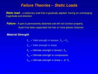
Failure Theories (5.3-5.8, 5.14). MAE 316 – Strength of Mechanical Components NC State University Department of Mechanical and Aerospace Engineering. Example. Static Loading. Failure theories

E N D
Failure Theories(5.3-5.8, 5.14) MAE 316 – Strength of Mechanical Components NC State University Department of Mechanical and Aerospace Engineering Failure Theory
Example Failure theory
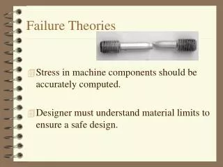
Static Loading • Failure theories • For a given stress state (σ1, σ2, σ3) use properties from a simple tension test (Sy, Sut) to assess the strength. y y T F x A x A diameter = d Failure Theory
Static Loading • For what values of T and F will the material fail if the yield strength is Sy? • If T = 0 • For T and F non-zero, how do we calculate an equivalent or effective stress to assess the strength? Failure Theory
Ductile vs Brittle Column Design
Maximum Normal Stress Theory (5.8) • Failure occurs when maximum principal stress exceeds the ultimate strength. • Primarily applies to brittle materials • Principal stresses: σ1, σ2, σ3 • Define σa, σb, σc where • σa= max (σ1, σ2, σ3) • σc = min (σ1, σ2, σ3) • σbis the value in between σy y τxy x σx Failure Theory
Maximum Normal Stress Theory (5.8) • For failure • σa= Sut if σa > 0 (where Sut is ultimate strength in tension) • σc= -Suc if σc < 0 (where Suc is ultimate strength in compression) • Case I: Uni-axial tension (bar, σx = σo = P/A, σy = τxy = 0) • σ1 = σo,σ2 = 0 & σ3 = 0 (plane stress) • σa = σo, σb = 0, σc = 0 • Failure when σo= Sut Failure Theory
Maximum Normal Stress Theory (5.8) • Case 2: Pure torsion (shaft, τxy = Tr/J, σx = σy = 0) • σ1 = +τxy,σ2 = -τxy & σ3 = 0 (plane stress) • σa = +τxy, σb = 0, σc = -τxy • Failure when τ xy= Sut or τ xy= Suc • Does not agree with experimental data. • Experimental data would show that failure occurs when τ ≈ 0.6 Sut. Failure Theory
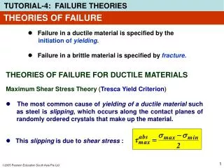
Maximum Shear Stress Theory (5.4) • Tresca yield criterion • Failure occurs when the maximum shear stress exceeds the yield strength (max shear stress in a tension test is Sy/2). • Applies to ductile materials. Failure Theory
Maximum Shear Stress Theory (5.4) • Case I: Uni-axial tension (bar, σx = σo = P/A, σy = τxy = 0) • σ1 = σo,σ2 = 0 & σ3 = 0 (plane stress) • σa = σo, σb = 0, σc = 0 • τmax = σo/2 = Sy/2 • Failure when σo= Sy • Case 2: Pure torsion (shaft, τxy = Tr/J, σx = σy = 0) • σ1 = +τxy,σ2 = -τxy & σ3 = 0 (plane stress) • σa = +τxy, σb = 0, σc = -τxy • τmax = τxy • Failure when τ xy= Sy/2 Failure Theory
Distortion Energy Theory (5.5) • von Mises theory • Failure occurs when • Applies to ductile materials. Failure Theory
Distortion Energy Theory (5.5) • Case I: Uni-axial tension (bar, σx = σo = P/A, σy = τxy = 0) • σ1 = σo,σ2 = 0 & σ3 = 0 (plane stress) • σo2 + σo2 = 2Sy2 • Failure when σo= Sy • Case 2: Pure torsion (shaft, τxy = Tr/J, σx = σy = 0) • σ1 = +τxy,σ2 = -τxy & σ3 = 0 (plane stress) • (τxy +τxy)2 + τxy2 + τxy2 = 2Sy2 • 6 τxy2 = 2Sy2 • Failure when τ xy= 0.577Sy • Agrees very closely with experiments! • Section 5.14 in the textbook summarizes failure theories. Failure Theory
Example Find the minimum allowable diameter, with a factor of safety of 2, using both Tresca and von Mises formulas. Assume Sy = 50,000 psi, P = 500 lbs, T = 1000 in-lb, and L = 5 in. y T Stress point x P + d Failure Theory
Stress Concentration Factor(3.13) MAE 316 – Strength of Mechanical Components NC State Department of Mechanical and Aerospace Engineering Stress Concentration Factor
Examples Stress Concentration Factor
Stress Concentration Factor (3.13) • Consider the following two stress analysis problems: h h b b P P P P d Stress Concentration Factor
Stress Concentration Factor (3.13) • For a plate with a hole, the maximum stress occurs around the hole. Stress Concentration Factor
Stress Concentration Factor (3.13) • Maximum stress is defined using a stress concentration factor, Kt. Stress Concentration Factor
Example For a plate with w = 2.0 in. and t = 1.0 in. subject to a 50,000 lb axial load, find the maximum stress for d = 0, 0.1 in., 0.5 in., and 1.0 in. Stress Concentration Factor
Stress Concentration Factor (3.13) • What if the hole is elliptical? σo σmax 2a (hole) 2b (crack) σo Stress Concentration Factor
Stress Concentration Factor (3.13) • This suggests that structures with sharp cracks could not sustain any level of applied stress without failure. • This cannot be correct – fracture mechanics analysis will resolve this. σo σo Stress Concentration Factor
Stress Concentration Factor (3.13) • Other types of stress concentrations (Appendix A-15) • Plate with fillet • Plate with notch • Shaft with fillet • Grooved shaft Stress Concentration Factor
Fracture Mechanics(5.12, 5.14) MAE 316 – Strength of Mechanical Components NC State University Department of Mechanical and Aerospace Engineering Fracture Mechanics
Fracture Mechanics (5.12) P y h b x L Fracture Mechanics
Fracture Mechanics (5.12) • For a sharp crack, Kt → ∞, σmax → ∞. • The conclusion is that P > 0 will lead to failure, but this is not reasonable. P crack a y h b x L Fracture Mechanics
Stress Intensity Factor (5.12) Figure 5-23 Crack deformation types: (a) mode I, opening; (b) mode 2, sliding; (c) mode III, tearing Fracture Mechanics
Stress Intensity Factor (5.12) • In fracture mechanics, design analysis is based not on stress, but stress intensity factor. • Stress intensity modification factors vary depending on load and geometry. • Refer to Figures 5-25 through 5-29 in the textbook. Fracture Mechanics
Stress Intensity Factor (5.12) • So, for the cracked plate shown previously Figure 5-26 Fracture Mechanics
Fracture Toughness (5.12) • Failure will occur when K ≥ KIc (KIc is fracture toughness, a material property). • “Failure” means the crack extends unstably and the structure fractures (i.e. breaks). Fracture Mechanics
Fracture Toughness (5.12) • In fracture mechanics, factor of safety can also be expressed as Fracture Mechanics
Fracture Toughness (5.12) • Two different analysis methods • To design conservatively for safety, we must do both analyses. Fracture Mechanics
Example • The cracked plate shown below is made of 4340 steel has Sy = 240 ksi and KIc = 50 ksi(in)1/2. Find the maximum allowable load, P, that can be applied to the beam without failure. • Given: b = 1 in, h = 2 in, L = 24 in, a = 0.25 in P crack a y h b x L Fracture Mechanics
Example • Find the stress intensity factor for a plate with a center crack if the average normal stress in the plate is 10 ksi. • Given: 2a = 3 in and 2b = 10 in, d=4 in Fracture Mechanics
Example • Find the stress intensity factor for a plate with an edge crack if the average normal stress in the plate is 10 ksi. • Given: a = 3 in and b = 10 in Fracture Mechanics
A Real-Life Example of Fracture Fracture Mechanics
A Real-Life Example of Fracture Fracture Mechanics