Download
1 / 26
260 likes | 422 Vues
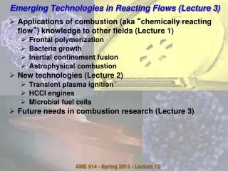
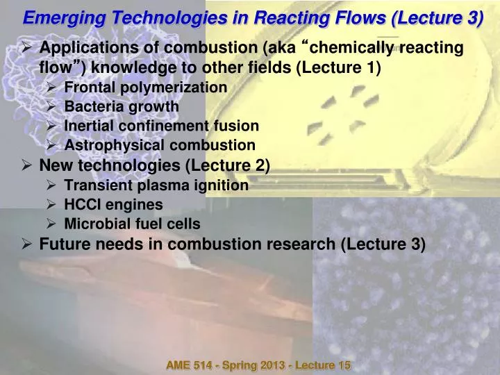
Emerging Technologies in Reacting Flows (Lecture 3 ). Applications of combustion (aka “ chemically reacting flow ” ) knowledge to other fields (Lecture 1) Frontal polymerization Bacteria growth Inertial confinement fusion Astrophysical combustion New technologies (Lecture 2)

E N D
Emerging Technologies in Reacting Flows (Lecture 3) • Applications of combustion (aka “chemically reacting flow”) knowledge to other fields (Lecture 1) • Frontal polymerization • Bacteria growth • Inertial confinement fusion • Astrophysical combustion • New technologies (Lecture 2) • Transient plasma ignition • HCCI engines • Microbial fuel cells • Future needs in combustion research (Lecture 3) AME 514 - Spring 2013 - Lecture 15
Combustion synthesis of thin-film photovoltaic cells • Courtesy of Prof. Hai Wang • Current photovoltaic (solar) cells are reasonably efficient but very expensive to produce (≈ $10/watt vs. $1/watt for conventional electric power); net cost of solar ≈ 5x conventional power • Dye-sensitized solar cells not as efficient but cheap to manufacture • First proposed by O’Regan and Grätzel (Nature 343, 737-740, 1991) • Somewhat like fuel cell • Anode: transparent, conductive glass, coated with TiO2 nanoparticles in turn coated with fluorescent dye to absorb incoming photons • Electrolyte: I- / I3- oxidation/reduction reaction – basically a diode so current can only flow one direction • Cathode: Pt-coated transparent, conductive glass AME 514 - Spring 2013 - Lecture 15
E (V) S* -0.5 maximum Voltage ~0.75 V 0.0 hu red (I-) ox (I3-) 0.5 Redox mediator 1.0 e- e- Dye-Sensitized Solar Cell Transparent conducting glass Transparent conducting glass TiO2 dye electrolyte e- S AME 514 - Spring 2013 - Lecture 15
TiO2 particle considerations • TiO2 has advantages over silicon - TiO2 “work function” such that once an electron jumps to conduction band it stays;cannot fall back down to valence band (if particle truly crystaline) • Ideal particle size < 10 nm • Too large: low surface/volume ratio, don’t get good electron collection • Too small: too many contacts between particles, causes high resistance to electron flow • Current technique for anode fabrication • Commercial TiO2 powder (>20 nm) • Making a paste/paint & screen printing • Sinter at 450 ◦C (glass substrate only) • Stain with dye • USC method • Particle synthesis and film deposition in one step • No need to sinter AME 514 - Spring 2013 - Lecture 15
Synthesis method – stagnation flame Tmax Flame Stabilizer Stagnation flame vO burner-stabilized flame Tubularburner Carrier gas Ar vO C2H4/O2/Ar Shielding Ar TTIP/Ar Particle properties controlled by Flame temperature (argon dilution) Reaction time (flow rate) Ti precursor concentration TTIP Electric mantle AME 514 - Spring 2013 - Lecture 15
Flame Structure (C2H4-O2-Ar, f = 0.4) Particle nucleation/ 2500 Stagnation surface (x = 3.4 cm) growth region 2000 (K) 1500 T 1000 500 500 Particle nucleation/ growth region 400 300 (cm/s) Axial Velocity 200 v 100 Laminar flame speed 0 10 0 CO H O 2 2 O 2 10 -1 C H 2 4 CO Mole Fraction 10 -2 10 -3 H 2 H Computations used the Sandia counterflow flame code and USC Mech II 10 -4 2.7 2.8 2.9 3.0 3.1 3.2 3.3 Distance from nozzle, x (cm) AME 514 - Spring 2013 - Lecture 15
Aspects of particle growth • Growth time limited to 2 ms because of thermophoresis (TP) – moves particles to from high T to low T in gas • On increasing T side of flame, convection is rapid and TP can’t hold particles in place against convection • As particle approaches stagnation plane, U decreases and TP force pushes particle along faster (about 1 m/s), limiting growth time and thus particle size • Very uniform residence time for on-axis and off-axis particles – characteristic of stagnation flow AME 514 - Spring 2013 - Lecture 15
Particle size distributions Increase Ti Precursor Concentration Particle size can be well controlled Size distribution widens as median size increases but the size variation still small compared to other methods AME 514 - Spring 2013 - Lecture 15
Flame Stabilized on Rotating Surface Want boundary layer thickness d~ (u/wrad)1/2 < distance from flame to stagnation surface, so rotation doesn’t affect particle formation & growth ~0.3 cm AME 514 - Spring 2013 - Lecture 15
Stationary vs. Rotating Stagnation Plate Rotating the stagnation surface results in smaller particles and narrower distributions AME 514 - Spring 2013 - Lecture 15
Comparison with commercial TiO2 • Tested under the standard AM1.5 solar light • Use Solaronix purple dye, comparisons made under comparable conditions • FSTS films (largely unoptimized) outperform Degussa powder with screening printing • Method allows continuous, reel-to-reel fabrication of DSSC photoanodes in one step AME 514 - Spring 2013 - Lecture 15
Future needs… • Inertial confinement fusion - What is optimal size of fusion shell to avoid instabilities yet allow ignition? • Hypersonic propulsion • Inlet designs (steady or PDEs) - minimize stagnation pressure losses, stress concentrations on airframe due to shocks • Mixers (steady) - how to get fuel and air mixed without massive stagnation pressure losses? • Detonation initiation schemes - transient plasma ignition or ??? • HCCI engines: identify “radical buffer” (analogous to pH buffer) to limit rate of heat release, allow slower combustion once reaction starts • Probably must not generate any solid particles • Probably must contain C, H, O, N atoms only AME 514 - Spring 2013 - Lecture 15
Future needs… • Transient plasma discharges • Possible way of exploiting faster burn in IC engines - reverse engineer engine for lower turbulence (lowers both burning rate and heat losses), restore high burning rate using transient plasma discharges • Need detailed chemical models like “GRI Mech” for ionized species • Microbial fuel cells - kinetic and transport laws for bacterial metabolism and electron production - what are the equivalents of • Navier-Stokes equations • Fick’s law of diffusion • Arrhenius law of reaction rates AME 514 - Spring 2013 - Lecture 15
Microbial fuel cell modeling - objective • Improve the mechanical, electrical, hydraulic, and diffusive aspects of the fuel cell until the bacterial activity is the only rate-limiting step • Computational, with experimental calibration & verification (both) • Toward this goal, study effects of • Anode and cathode geometry - shape, thickness, porosity, electrical contacts • Biofilm community • Species & strain • Growth method - anaerobic, aerobic or with a cell voltage bias • Planktonic bacteria • Mixing rates in anode and cathode chambers • Anolyte - nutrient type and concentration, pH • O2 crossover - membrane thickness, N2 purging AME 514 - Spring 2013 - Lecture 15
Computational model • FLUENT computational fluid dynamics software package - flow, convective & diffusive transport, chemical reaction • One-dimensional, steady state (easily extended to 2D or 3D, transient) • 3-step chemical model • (Slow) oxidation reaction occur only at the anode Nutrient (R1) + bacteria Product (P1) + 2H+ (I) + 2e- + bacteria • (Faster) reduction reaction occur only at the cathode Oxygen (R2) + 4H+ (I) + 4e- + Pt 2H2O (P2) + Pt • O2 crossover - competition with anode - no power production 2 Nutrient (R1) + Oxygen (R2) + bacteria 2 H2O (P2) + bacteria • Membrane approximated as permeable only to selected species (intermediate (I) = H+, Reactant 2 (R2) = O2) • Anode and cathode reaction rate constants adjusted to get agreement between model and experiment at ONE condition, same rate constants applied for varying parameters AME 514 - Spring 2013 - Lecture 15
Model parameters • Dimensions • Anode and cathode chamber sizes • Anode and cathode thickness and surface area per unit volume • Membrane thickness • Concentrations • Nutrient, dissolved O2 • Reaction rate constants (connection with “microscale” modeling effort, A. Lüttge) • (1): per unit molarity per unit surface area • (2): per unit (molarity)2 per unit surface area • (3): per unit (molarity)2 • Diffusivities of all species • Boundary conditions (next slide) AME 514 - Spring 2013 - Lecture 15
2 4 Cathode electrode Reaction: R2 + 4 I 2 P2 Oxygen H+ H2O Molecular diffusion Anode electrode with bacteria Reaction: R1 2 I + P2 Nutrient H+ Waste Molecular diffusion 1 3 5 Anode Chamber Turbulent diffusion Membrane Reduced diffusion Cathode Chamber Turbulent diffusion Cathode Wall R2 = 8.3x10⁻⁶ M/m3 I = No Flux Others = 0 Anode Wall R1 = 8.6x10⁻⁶ M/m3 I = No Flux Others = 0 5mm (20cells) 5mm (20cells) 5mm (20cells) 5mm (20cells) 100μm (10 cells) 1D FLUENT computational model 1 2 3 4 5 AME 514 - Spring 2013 - Lecture 15
Nutrient concentration profiles Nutrient Boundary conditions: 8.6e-3 at the Anode wall 0 in the Cathode wall Consumption No diffusion through the membrane Concentration (M) AME 514 - Spring 2013 - Lecture 15
Product &intermediate concentration profiles Anode reaction R1 P1 + 2 I Nutrient Part. Nutrient H+ Concentration of P1 (M) Concentration of I (M/m3) AME 514 - Spring 2013 - Lecture 15
Computed effect of nutrient diffusivity • N2 flow alone in anode chamber alone does not provide reaction-limited power, but magnetic stirring does (consistent with experiments) AME 514 - Spring 2013 - Lecture 15
Experiments - apparatus • 10 complete cells & data acquisition • Glass anode & cathode chambers • Carbon felt electrodes; Pt coating on cathode • Ports for N2 (anode) & air (cathode) • LabView data acquisition - automatic generation of polarization curves AME 514 - Spring 2013 - Lecture 15
Results - transport effects • N2 flow noticeably increases power due to stirring, but magnetic stirring much more effective AME 514 - Spring 2013 - Lecture 15
Scaling – “small,”“average,”“large”MFCs • “Large”scales • Turbulent flow - more rapid mass transfer • Buoyancy effects - more rapid mass transfer • “Average”scales • Laminar flow - slower mass transfer • “Small”scales • Diffusion rate high (~ D/d2) • Characteristic reaction rates independent of scale • Multiple transitions between mixing-limited and reaction rate-limited operation as scale changes AME 514 - Spring 2013 - Lecture 15
Future needs… • “In situ” enhanced oil recovery via subsurface combustion • See e.g. Mahinpey, N., Ambalae, A., Asghari,K., “In situ combustion in enhanced oil recovery (EOR): A review” Chem. Eng. Commun. Vol. 194 pp. 995-1021 (2007) • Heavy-oil reservoirs containing high-viscosity oil are impossible to produce via conventional pumping • Viscosity decrease via steam injection expensive & of limited effectiveness • Can inject air and combust a portion of oil • Has seen limited field use but can be effective • Limited laboratory experiments, in small diameter tubes • Real situation: large cross-section – instabilities • Similar to “filtration combustion” of porous solid • Very similar to flames in Hele-Shaw cell (see lecture 8) • Flow described by Darcy’s Law • Buoyancy (RT), thermal expansion (DL), viscosity change (ST) instabilities • …. But a non-premixed, 3-phase (air, oil, inert porous solid) system AME 514 - Spring 2013 - Lecture 15
Future needs… • “In situ” enhanced oil recovery via subsurface combustion http://www.netl.doe.gov/technologies/oil-gas/publications/eordrawings/BW/bwinsitu_comb.PDF AME 514 - Spring 2013 - Lecture 15
Future needs… M. V. Kök, G. Guner, S. Bagci, Oil Shale, Vol. 25, No. 2, pp. 217–225 (2008) AME 514 - Spring 2013 - Lecture 15