Download
1 / 44
490 likes | 1.4k Vues
Computer Graphics Hardware Input/Output Technologies Display Hardware Hard Copy devices Printers, plotters Transient displays LCD Monitors, CRT Monitors, projectors …. Wooden Mirrors?! Cathode ray tube Most common is Cathode Ray Tube (CRT) monitor

E N D
Computer Graphics Hardware Input/Output Technologies
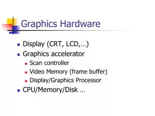
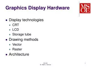
Display Hardware • Hard Copy devices • Printers, plotters • Transient displays • LCD Monitors, CRT Monitors, projectors • …. Wooden Mirrors?!
Cathode ray tube • Most common is Cathode Ray Tube (CRT) monitor • Horizontal and vertical deflectors focus an electron beam on any spot on a phosphor coated screen Electrons hit the screen phosphor molecules and excite them Karl Ferdinand Braun 1897 – Cathode Ray Oscilloscope
Phosphors • Most phosphors relax back to the ground state by emitting a photon of light which is called flourescence, which decays in under a millisecond • Some molecules may be further excited, and emit a light call phosphorescence, which decays slower, but still rapidly (15-20 milliseconds) • Therefore, the screen must be refreshed by redrawing the image • They also are characterized by their persistence (time to decay of emitted light) • High persistence cheap and good for text, bad for animation • Low persistence, good for animation, but need high refresh rate
Colour Systems • Phosphors have a colour. Colour systems have groups of 3 different phosphors, for red, green and blue. Additive Colour. • 3 Electron guns used, for R G and B • Each pixel consists of 3 dots of phosphor, arranged as triangle • Combining different intensities of phosphors can generate different colours Standard Dot-trio Hitachi EDP SONY Trinitron CRT NEC Hybrid Mask
Shadow Masks Shadow maskholes are arranged so that each beam can only excite it’s own color phosphor
B A Vector Display Devices • A.K.A. Vector Scan Displays, Random Scan Devices, Line Plotters • The electron beam directly draws the picture e.g. DrawLine(A, B): Turn beam off, move to A. Turn beam on, move to B.
Vector Graphics • Although Vector Displays no longer as widely used, it is still common practice to deal with certain types of images in terms of vector graphics. • A Vector File contains a list of entries each of which describes an element of a picture. • How a picture element is described depends on what type of element it is. e.g. a line segment can be described in terms the co-ordinates of its two end points, its thickness, and its style (solid, dotted, etc.) Also curves and shapes. • Example: postscript files (PS/EPS) • To display on a RASTER device the graphic needs to be rasterized
/ok_Ellipses { %on stack: %xCenter yCenter xOffset yOffset width height weight howMany [color array] aload pop setcmykcolor /ok_HowMany exch def /ok_Weight exch def /ok_Height exch def /ok_Width exch def /ok_yOffset exch def /ok_xOffset exch def /ok_yCenter exch def /ok_xCenter exch def /ok_Angle 360 ok_HowMany div def /ok_xR ok_Width 2 div def /ok_yR ok_Height 2 div def /ok_x1 ok_xR ok_xR .552292 mul sub def /ok_y1 ok_yR ok_yR .552292 mul sub def ok_Weight setlinewidth gsave ok_xCenter ok_yCenter translate ok_HowMany { ok_Ellipse ok_Angle rotate } repeat stroke grestore } def %!PS-Adobe-3.0 EPSF-3.0 %%BoundingBox:0 0 288 288 %%ColorUsage: Color %%DocumentProcessColors: Cyan Magenta Yellow Black /ok_Ellipse { ok_xOffset ok_yOffset moveto ok_x1 0 ok_xR ok_y1 ok_xR ok_yR rcurveto 0 ok_y1 ok_x1 neg ok_yR ok_xR neg ok_yR rcurveto ok_x1 neg 0 ok_xR neg ok_y1 neg ok_xR neg ok_yR neg rcurveto 0 ok_y1 neg ok_x1 ok_yR neg ok_xR ok_yR neg rcurveto closepath } def
Raster Graphics • An image made up of many small regularly placed cells (pixels) • Stored as an array of numerical values commonly called a pixelmap (or bitmap)
Raster Scan Devices • Scans the screen from top to bottom in a regular pattern (common TV technology) • A Raster is a matrix of pixels (picture elements) covering the screen • The electron beam is turned on/off so the image is a collection of dots painted on screen one row (scan line) at a time.
Frame Buffer • An image is stored in a special graphics memory area called a frame buffer (or bit map) where each memory location corresponds to a pixel • A display processor scans this memory and controls the electron beam at each pixel accordingly • For a monochrome system, each pixel is either on or off, so only one bit per pixel is required, the electron beam is either on or off • For grayscale images, 8 bits per pixel gives 256 different intensities of gray • For an ideal colour display there should be 8 bits/pixel giving a total of 24 bits per pixel and about 16,000,000 displayable colours. Such a display is called a true colour display
1 Bit Per Pixel 2 Bits Per Pixel or 2 binary digits 8 Bits Per Pixel or 8 digits in binary 24 Bits Per Pixel 1 or 0 in binary (on/off) 22 = 4 possible combinations: 00, 01, 10, 11 00000000 to 11111111. 28 = 255 different possible values 000000000000000000000000 to 111111111111111111111111. i.e. 224 or 16 million possible values Bits Per Pixel
Memory Usage Example Black-and-white Greyscale True-colour 8x8x1 = 64 bits 8x8x8 = 512 bits 8x8x24 = 1536 bits
Colour Lookup table (CLUT) • In many colour raster systems, the display controller includes a colour lookup table. • The value of a pixel in the frame buffer is not used to directly control the beam, but is an index into the LUT • The entry in the LUT is used to directly control the colour of the pixel • Eg. If we use 1 byte (8 bits) per pixel in frame buffer, 6 bits for each of R,G and B in LUT, then an application can choose 256 (28) colours out of 262,144 (26x26x26) available colours. 8x8x8 = 512 bits But a large “range” of colours
Direct Color Indirect Color with Colour Lookup Table 256 shades DC: 24 bits per pixel required 7.2M; CLUT:256 entries 3.6M 32 shades DC: 18 bits per pixel required 5.4; CLUT:64 entries 1.8M 16 shades DC: 12 bits per pixel required 3.6M; CLUT:16 entries 1.2M
Rasterization • Geometric and Mathematical Data structures typically in vertex coordinates not dependent on resolution • We must convert from typical continuous representation to discrete
Rasterization • Mostly based on Interpolation: • X and Y projected coordinates • Red, green and blue values • Intensity values • Alpha values • Z values (depth) • Colour index values • Surface Normals • Texture map coordinates
RAMDAC • Random Access Memory Digital-to-Analog Converter, • A single chip on video adapter cards. • The RAMDAC's role is to convert digitally encoded images into analog signals that can be displayed by a monitor. • A RAMDAC actually consists of four different components • SRAM to store the color map • three digital-to-analog converters (DACs), one for each of the monitor's red, green, and blue electron guns.
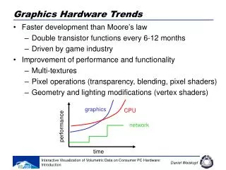
Raster Scan Systems: Conclusion • Advantages of Raster Scan systems: • Low cost (cheap ram used for bitmaps) • Refresh rate independent of image complexity • Handles colour and filled areas images -> high refresh • Regular repetitive => easier and cheaper to implement. • Disadvantages • Models must be scan converted. Often this can’t be reused so must do this every frame. • Aliasing • Requires large refresh buffers even for small or simple images. • Images bound to a certain resolution
Vector Displays • Advantages: • High resolution and not discretized • Less Storage Space • Less Transfer Time (usually) • Disadvantages • Limited colourcapability. Problems with filled areas and shading. • Flicker occurs as complexity of image increases. • Vector data needs some processing before display • Processing required before obtaining the Vector representation • Wastage in Overlapping areas
LCD Technology • Liquid Crystal Display • A transmissive technology • Works by letting varying amounts of a fixed-intensity white backlight through an active filter • Organic crystals that are aligned in a certain way in layers affect light passing through them • When external force is applied they realign themselves • This is used to change polarisation and filter light
LCD displays • Two layers of polarizers are placed at right angles to each other. • With layers of LCD between the two polarizing layers. • LCD crystals are aranged in a twisted spiral layout. • After light passes through first layer, the LCD crystals change the plane of the light’s vibration so that it can pass through the second layer.
LCD displays • When an electric field is passed through the LCD layers, they align themselves with the field and untwist. • Polarised light is let through the crystals unhindered but becomes blocked by the second polarizer layer. • The relevant pixel then becomes darkened out
Passive Matrix LCD • Traditional LCD systems used an array of LCD nodes that could be twisted and untwisted based on simple grid controlled by column and row inputs that turned the relevant pixel on and off • Simple but slow refresh • And neighbouring pixels become affected to some degree causing “fuziness” Positive voltage applied Ground line activated Sub-Pixel corresponding to relevant row and column becomes disactivated.
TFT Displays • Thin film transistor (TFT) displays also called Active Matrix LCDs are a more flexible variant of the LCD technology. • Each pixel is controlled individually by using one or more transistors to control electric field for each pixel. • Besides the polarising sheets and cells of liquid crystal, there is a matrix of thin-film transistors (TFTs) which store the electrical state of each pixel on the display while all the other pixels are being updated • Advantage of TFTs: Light Weight, Very Good Image Quality, wide colour range and good response time.
Advantages Fast response (high resolution possible) Full colour (large modulation depth of E-beam) Saturated and natural colours Inexpensive, matured technology Wide angle, high contrast and brightness Disadvantages Large and heavy (typ. 70x70 cm, 15 kg) High power consumption (typ. 140W) Harmful DC and AC electric and magnetic fields Flickering at 50-80 Hz (no memory effect) Geometrical errors at edges CRT Displays
Advantages Small footprint (approx 1/6 of CRT) Light weight (typ. 1/5 of CRT) Low power consumption (typ. 1/4 of CRT) Completely flat screen - no geometrical errors Crisp pictures - digital and uniform colors No electromagnetic emission Fully digital signal processing possible Large screens (>20 inch) on desktops Disadvantages High price (presently 3x CRT) Poor viewing angle (typ. +/- 50 degrees) Low contrast and luminance (typ. 1:100) Low luminance (typ. 200 cd/m2) LCD Displays
Logical Input Devices • A Classification of Input Devices to enable some level of abstraction so they can be supported by various graphics systems • Diverse variations of input devices exist • It is useful to classify object in terms of whatA it does • This provides level of abstraction • Enhances portability (device independent design of interface) • Shields application from physical details
Classes of Logical Input Devices • Locator/ Pick • to indicate a position or orientation (subclasses) • to select a displayed entity • Valuator • to input a single real number • String • To input a character string • Returns key with specific meaning • Letters, Numbers etc. • Choice • To select from a set of possible actions or choices • Often return sensory feedback e.g. lights, clicks
Physical Input Devices (1) • Keyboard: string/choice input • Gamepad: choice • Mouse: pick/locator device with relative positioning and indirect input. • Tablet: pick/locator device with absolute positioning and indirect input. • Joystick/Trackball: locator/valuator • Knobs (e.g. Volume control): valuator devices
Drivers • Nowadays days we have a lot more diverse input hardware, some of which don’t fit well into the Logical Input Device Classes • e.g.: bat, blow-suck tube, brain-computer interface, chording, dataglove, electronic ink, eye-tracking, foot pedal, gesture, joystick, light pen, motional input device, mouthstick, OCR, paddle, pointing device, puck, stroke recognition, tongue-activated joystick, touch interactive display, touch tablet, touchpad, trackball • Logical Input Devices were invented for the GKS standard graphics system. These days dedicated drivers for all pieces of hardware can be written that talk more directly to your Operating system.
3D Model Acquisition • 3D laser scanner • Digitizer • Video based modelling
Motion Capture VICON Optical Motion Capture System
Force Feedback Devices • Combine input and some degree of output • Useful for navigating simulated virtual environments • Range of feedback types: • Tactile feedback • Haptic Feedback • Force Feedback
Eye Trackers EYELINK head and Eye-tracking System
CAVE: Cave Automatic Virtual Environment HMD (Head Mounted Display) HITLabs/Microvision Googgles