Download
1 / 42
460 likes | 1.12k Vues
Presentation Overview. ACR Accreditation Program and PhantomAccreditation RequirementsTable I and SMPTE PatternAlignmentModule 1 Module 2 Module 3Module 4 CTDI Data RequirementsCTDI Data sheet. ACR CT Accreditation. Started in 2002Performance evaluation based on the MTFs current clinical protocolsRequirementsApproximately 20 images (Film page)CT parameter table (Table 1)Data sheets ( Data taken from each module) 3 Excel Worksheets (CTDI data).

E N D
1. The American College of Radiology (ACR) Phantom and Performance Evaluation for CT Accreditation Scott Jones, MS
LTJG, MSC, USNR
NNMC Bethesda
3. ACR CT Accreditation Started in 2002
Performance evaluation based on the MTFs current clinical protocols
Requirements
Approximately 20 images (Film page)
CT parameter table (Table 1)
Data sheets ( Data taken from each module)
3 Excel Worksheets (CTDI data)
5. ACR CT Accreditation Phantom Gammex-RMI Model 464
Constructed primarily of a water equivalent material
Solid phantom containing 4 modules
4 cm wide x 20 cm diameter
External alignment markings (centering phantom)
Head, Foot, and Top markings
Optional phantom support base
6. ACR CT Accreditation Phantom
Designed to examine a broad range of image quality parameters
Position accuracy
CT # accuracy
Slice width
Low contrast resolution
High contrast (spatial) resolution
CT # uniformity
Image noise
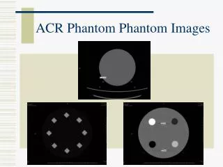
7. ACR CT Accreditation Phantom
11. ACR CT Accreditation Requirements
12. Table I Critical element of submission process that is representative of sites routine clinical scans
Consistent with image data
Protocols
Head
HRC
Adult Abdomen
Pediatric Abdomen (If applicable)
14. SMPTE Test Pattern SMPTE test pattern (required)
Demonstrates the quality of submitted hard copy films
Failure to submit SMPTE results in automatic failure
Alternate patterns are accepted, but not recommended
15. Essential Criteria First box of each film sheet
95% visible
5% visible
Whites and blacks must not be saturated
No aliasing of bar patterns
16. Alignment Modules 1 and 4
HRC protocol (< 2 mm scan width)
Scan phantom at S0 and S120
Scan 1mm superior and inferior to each mark
WW = 1000 and WL = 0
Proper alignment
4 BB�s seen in one image with similar appearance in both module 1 and 4
The longest wire centrally located (+/- 1 wire) on both top and bottom ramps
Must pass alignment test to proceed
19. CT Number Calibration Initial alignment at Module 1(foot)
S0 or 0 position
Embedded test objects in Module 1
Low density polyethylene (LDPE)
Acrylic
Bone equivalent
Air
Solid Water
20. CT Number Calibration Scan ACR phantom at S0
Adult abdomen protocol
Scan in Axial mode
Multislice scanners
Center scan so that one image is centered at S0
DFOV 21 - 25 cm
Circular ROIs � 200 mm2 over each peg
21. CT Number Calibration WW = 400, WL = 0
Polyethylene
-107 to -87 HU
Water
-7 to +7 HU (+/-5 HU)
Acrylic
+110 to +130 HU
Bone
+850 to +970 HU
Air
-1005 to -970
23. Slice Thickness Adult abdomen protocol (axial scan)
HRC slice thickness and ~3 mm, 5 mm, and 7 mm slice thickness at same window and level settings as before
Mean CT of water (-7 to +7 HU)
Verify slice thickness by counting pins
Count pins that appear to be 50% as bright as center pin and divide by 2
0.5 mm apart
Slice thickness must be within 1.5 mm of prescribed thickness
24. Water vs. kVp Adult abdomen scan (axial)
Repeat previous scan at all kVp settings.
Mean CT number of water should stay within the previous stated range (-7 to +7 HU)
26. Low Contrast Resolution Module 2
Adult abdomen protocol
DFOV 21- 25 cm
27. Low Contrast Resolution Axial Acquisition
Acquire 3 axial images at the following positions
S40 or 40 mm Superior
S80 or 80 mm Superior
S120 or 120 mm Superior
Helical Acquisition
Start scan at S40
End scan at S120
Choose a 5 mm scan reconstruction interval to ensure that one image is reconstructed at the center of modules 2, 3, and 4
Module 3 and 4 images will be analyzed in later section
28. Low Contrast Resolution View image located at Module 2 center
WW = 100 WL = 100
Determine smallest diameter of cylinder set in which ALL FOUR are clearly delineated
2, 3, 4, 5, and 6 mm
6 mm cylinder set must be visualized
29. Low Contrast Resolution 100 mm2 ROI
Inside 25 mm cylinder
Just outside the 25 mm cylinder
Calculate CT number difference
� 6 HU difference
Repeat module 2 (low contrast) evaluation using the routine head protocol
31. Uniformity, Noise, and In Plane Distance Module 3
View previously acquired Adult abdomen images
WW = 100 WL = 0
400 mm2 ROIs at center and four edge positions (12, 3, 6, and 9 o�clock)
One ROI diameter from the edge
32. Uniformity, Noise, and In Plane Distance Record Mean CT numbers from all 5 ROIs
Record Center ROI standard deviation
Calculate the Uniformity value
ABS(Center Mean CT � Edge Mean CT)
Difference should be < 5HU for all four edge ROIs
Center Mean CT number should be (-7 to +7)
33. Uniformity, Noise, and In Plane Distance Examine the image for artifacts such as rings or streaks
Record the presences and appearance of artifact.
Measure in plane distance
Two BBs at the center of module 3.
100 mm
36. High Contrast Resolution Previously acquired adult abdomen image
WW = 100 WL = 1100
Values can be adjusted slightly to optimize the visualization of the bar patterns
Record the highest spatial frequency visualized
4, 5, 6, 7, 8, 9, 10, and 12 lp/cm
Adult Abdomen Protocol
The 5 lp/cm must be clearly resolved
Repeat test using the HRC protocol
6 lp/cm must be clearly resolved
38. CTDI Data 3 clinical protocols tested
Adult Head
Adult Abdomen
Pediatric Abdomen
Axial scans must be used
kVp, mA, exposure time, N, and T must remain the same
39. CTDI Data CTDI Phantoms
16 cm (Head and Peds Abdomen)
32 cm (Adult Abdomen)
Location
ABD protocols on table top
Head protocol in head holder
Images
Non chamber holes must be filled
Phantom must be centered
40. CTDI Data Measurements
Average of 3 center measurements
3 measurements must be within 5%
Average of 3 measurements at 12 o�clock position
3 measurements must be within 5%
CTDI Reference Values
Based on AAPM & ICRP Reports
No pass or fail criteria on dose
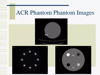
41. CTDI Phantom Image
42. Reference Values CTDIw
Head
60 mGy
Abdominal
35 mGy
Peds Abdominal
25 mGy
43. Common Operator Errors
44. References
45. Questions?