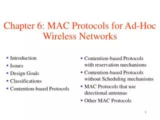
Wireless MAC protocols
Wireless MAC protocols. Prof. Malathi Veeraraghavan Elec. & Comp. Engg. Dept/CATT Polytechnic University mv@poly.edu. EL604: Wireless & Mobile Networking. Classification of wireless MAC protocols. Wireless MAC protocols. Fixed-assignment schemes. Random-access schemes.


Wireless MAC protocols
E N D
Presentation Transcript
Wireless MAC protocols Prof. Malathi Veeraraghavan Elec. & Comp. Engg. Dept/CATT Polytechnic University mv@poly.edu EL604: Wireless & Mobile Networking
Classification of wireless MAC protocols Wireless MAC protocols Fixed-assignment schemes Random-access schemes Demand assignment schemes Circuit-switched CL packet-switched CO packet-switched
Outline • Need for wireless MAC protocols • Obtain assignment of resources per call • ala circuit switching • fixed assignment • Obtain assignment of resources per packet • ala packet switching • CL flavor: random-access • CO flavor: demand-assignment
Random access MAC protocols • Comparable to connectionless packet-switching • No reservations are made; instead a wireless endpoint simply starts sending data packets • What can happen?
Answer • Collision • Need to avoid collisions or detect collisions and retransmit • What’s the cost of being too careful to avoid collisions? • Utilization will be sacrificed
Various random-accessMAC schemes • ALOHA • Slotted ALOHA • CSMA • CSMA/CD • CSMA/CA
ALOHA • Simplest scheme • True free-for-all. When a node needs to send, it does so. It listens for an amount of time equal to the maximum round trip delay plus a fixed increment. If it hears an acknowledgment, fine; otherwise it resends after waiting a random amount of time. After several attempts, it gives up. • Low delay if light load • Max. utilization: 18%
Analysis of ALOHA First transmission Retransmission • tprop: maximum one-way propagation delay between any two stations • X = L/R, L: packet length (constant) R: rate • S: Throughput (also number of new arrivals/X sec if we assume that all packets eventually make it) • G: arrival rate of new + retransmitted packets/X sec; Poisson arrival processes • Probability of successful transmission is that there are no additional transmissions in the vulnerable period of 2X • Y: random variable denoting number of total arrivals in 2X seconds t-X t t+X t+X+2tprop t+X+2tprop+B backoff period vulnerable period
Analysis of ALOHA contd. • The throughput S is the total arrival rate G times the probability of there being no collision • The average delay depends on average number of transmission attempts per packet • The average number of unsuccessful attempts G/S-1 • Average delay is approximated by
ALOHA throughput Maximum throughput is 18% at G = 0.5
Slotted ALOHA • Competition to send only occurs at the start of each slot (equal to X) • Vulnerable period is X (not 2X as in ALOHA) • What is maximum throughput?
CSMA • Carrier Sense Multiple Access • sense carrier • if idle, send • wait for ack • If there isn’t one, assume there was a collision, retransmit • Vulnerable period: one tprop
Different techniques • 1-persistent: • if busy, constantly sense channel • if idle, send immediately • if collision is detected, wait a random amount of time before retransmitting • Non-persistent: • sense channel when station has a packet to send • if busy, wait a random amount of time before sensing again; • if idle, transmit as soon as it is idle • collisions reduced because sensing is not immediately rescheduled • drawback: more delay • p-persistent: combines 1-persistent goal of reduced idle channel time with the non-persistent goal of reduced collisions. • sense constantly if busy and the station needs to send a packet • when the channel becomes idle, transmit packet with probability p • with probability 1-p station waits an additionaltprop before sensing again
CSMA/CD • Ethernet (also 802.3) standardizes the 1-persistent CSMA/CD multi-access control protocol. • Each station listens before it transmits. • If the channel is busy, it waits until the channel goes idle, and then it transmits. • If the channel is idle it transmits immediately. Continue sensing. • If collision is detected, transmit a brief jamming signal, then cease transmission, wait for a random time, and retransmit. • collision detection is not by waiting for an ACK
Collisions in Ethernet • The collision resolution process of Ethernet requires that a collision is detected while a station is still transmitting. • Assume: max. propagation delay on the bus is a.
Collisions in Ethernet • Restrictions: Each frame should be at least twice as long as the time to detect a collision (2 · maximum propagation delay).
CSMA/CD • CSMA/CD: • In CSMA, if collision occurs, need to wait till damaged frames have fully propagated. For long frames compared to propagation delay, this could lead to significant waste of capacity. So add collision detection. • Rule: Frames should be long enough to allow collision detection prior to the end of transmission
Exponential Backoff Algorithm • If a station is involved in a collision, it waits a random amount of time before attempting a retransmission. • The random time is determined by the following algorithm: • Set “slot time” to 2a. • After first collision wait 0 or 1 time unit. • After i-th collision, wait a random number between 0 and 2 i-1 time slots. • Do not increase random number range if i=10. • Give up after 16 collisions.
Wireless 802.11 LAN • Uses CSMA/CA • Why CA and CD? • Difficult to detect collisions in a radio environment – why? • Hidden station problem: • Two mutually far away stations A and C want to send to B. • At A and C, channel appears idle • But collision occurs at B
Why is it difficult to detect collisions in a radio environment? • A transmitting station cannot effectively distinguish incoming weak signals from noise and the effects of its own transmission; need a full duplex radio to listen and transmit on same frequency (not true in FDD systems)
Mechanisms for CA • Use of Request-To-Send (RTS) and Confirm-to-Send (CTS) mechanism • When a station wants to send a packet, it first sends an RTS. The receiving station responds with a CTS. Stations that can hear the RTS or the CTS then mark that the medium will be busy for the duration of the request (indicated by Duration ID in the RTS and CTS) • Stations will adjust their Network Allocation Vector (NAV): time that must elapse before a station can sample channel for idle status • this is called virtual carrier sensing • RTS/CTS are smaller than long packets that can collide • Use of InterFrame Spaces (IFS)
stretching CP CFP Frame CFP Super-frame Foreshortened CFP 802.11 MAC • IEEE 802.11 combines a demand-assignment MAC protocol with random access • PCF (Point Coordination Mode) – Polling • CFP (Contention-Free Period) in which access point polls hosts • DCF (Distributed Coordination Mode) • CP (Contention Period) in which CSMA/CA is used
DCFDistributed Coordination Function • This mode of 802.11 is a random access MAC • When a node needs to send data, it senses the medium. If idle, wait for a period of DIFS and if the medium is still idle after DIFS, send immediately. • If when the medium is sensed it is busy; then • wait for medium to be idle for a DIFS (DCF IFS) period • then decrement backoff timer until • medium becomes busy again; freeze timer, OR • timer reaches 0; transmit frame • if two stations have their timers reach 0; collision will occur; for every retransmission attempt, increase the contention window (CW), idle period after a DIFS, exponentially; 2i –1 starting with CWmine.g., 7, 15, 31.
DIFS DIFS SIFS CW Random backoff time DCF mode transmission without RTS/CTS Data source Ack destination NAV other Defer access Exercise: Show timing diagram for DCF mode with RTS/CTS
DCF MAC • Send immediately (after DIFS) if medium is idle • If medium was busy when sensed, wait a CW after it becomes idle (because many stations may be waiting when medium is busy; if they all send the instant the medium becomes idle, chances of collision are high)
PHY layer • Three physical layer specifications are part of 802.11 • Spread spectrum • Frequency hopping (FH) • Direct Sequence (DS) • Infrared (IR)
FH • What is FH? • Modulate the data signal such that it occupies different frequency bands as transmission progresses • e.g., send a song over many FM radio channels with some dwell time per channel • Why not FDMA? • Multipath fading affects narrow frequency bands so that some channels offer very poor transmission • In FH, time spent in each channel is small
802.11 FH PHY • 79 non-overlapping 1Mhz channels used • 1Mbps signals transmitted over the 2.4Ghz band • 2400 – 2483.5Mhz • 83.5 Mhz of bandwidth (US: starts 2.402Ghz to 2.480 – so 79) • A channel hop occurs every 224 s • 78 hopping patterns • Divided into 3 sets of 26 patterns each • The sets are designed to avoid prolonged collision periods between hopping sequences in a set • Hopping patterns collide 3 times on average, and 5 times in the worst case over a hopping cycle; each hop is a jump of a minimum of 6 channels • Each 802.11 LAN must use a particular hopping pattern • The hopping patterns allow for 26 networks to be collocated and still operate simultaneously
+1 +1 +1 +1 +1 +1 -1 -1 -1 -1 -1 -1 -1 DS • Modulate data signal by a signal that occupies a much larger bandwidth • Chip rate: time to transmit a +1 or –1 • To transmit a data bit, need 11 chip times • 11 chip Barker sequence To transmit +1, send To transmit -1, send +1 +1 +1 +1 +1 -1 -1 -1 -1 11 symbol times 11 symbol times
802.11 DS • Takes a 1Mbps data signal and converts it into a 11 Mbps signal • 11 channels in the 2.4Ghz band (5Mhz spacing) • Channels separated by center frequencies at least 30Mhz apart can operate without interference • If total bandwidth is only 83.5 Mhz, only 3 802.11 LANs using DS can have overlapping cells • FCC only allocates between 2412 and 2462
Ad-hoc vs. infrastructure based • Ad-hoc • No fixed network infrastructure needed • A wireless endpoint sends and all nodes within range can pick up signal • Each packet carries destination and source address • How do you know addresses of nodes in your region? • Infrastructure mode • Access point receives and relay packets • In 802.11, how does a node know whether to send a packet toDS or directly? – What is the DS?
Extended Service Set (ESS) Distribution System (DS) Access points (AP) Basic Service Set (BSS) Infrastructure based architecture • Independent BSS (IBSS): has no AP • adhoc mode; only wireless stations • Infrastructure BSS defined by stations sending Associations to register with an AP
Address 1 Address 2 Address 3 Address 4 Seq. control Pwr Mgmt More Frag More Data Order Retry WEP Type 802.11 MAC frame format bytes 2 2 6 6 6 2 6 0-2312 4 Frame control Duration/ ID FCS Frame body MAC header Protocol version To DS From DS Sub-type bits 2 2 4 1 1 1 1 1 1 1 1
Field explanations • Type/sub-type field indicates the type of message • Management: • Association/Authentication/Beacon • Control • RTS, CTS, CF-end, ACK • Data • Data only, or Data + CF-ACK, or Data + CF-Poll or Data + CF-Poll + CF-ACK
Field explanations • To DS and From DS • More Frag: 802.11 supports fragmentation of data • More Data: In polling mode, station indicates it has more data to send when replying to CF-POLL • RETRY is 1 if frame is a retransmission; WEP (Wired Equivalent Privacy) • Power Mgmt is 1 if in Power Save Mode; Order = 1 for strictly ordered service
Field explanations • Duration/ID: Duration in DCF mode/ID is used in PCF mode • Address fields RA: Receiver Address TA: Transmitter Address DA: Destination Address SA: Source Address BSSID: MAC address of AP in an infrastructure BSS
4 bits 12 bits 2 2 6 4 bytes Fragment number Sequence number Frame control Duration RA FCS Field explanations Sequence control field ACK frame • Sequence control • Sequence number remains the same for all retransmissions of an data unit • Sequence numbers of all fragments of a data unit are the same • Fragmentation Threshold determines size of fragments • Maximum size of MAC frame payload is 2312 bytes • Not included in ACK frame • Broadcast and multicast frames are not ACK’ed
Features of 802.11 MAC protocol • Supports MAC functionality (address fields) • Error detection (FCS) • Error correction (ACK frame) • Fragmentation (More Frag) • Flow control: stop-and-wait
Registration • Why should an endpoint register with the access point: • allows the AP to distribute frames to a station • Association, reassociation and disassociation • Views of 802.11 • view 802.11 as a wireless local area network • view 802.11 link as a wireless access link
Data flow • Case 1: Packet from a station under one AP to another in same AP’s coverage area • Case 2: Packet between stations in an IBSS • Case 3: Packet from an 802.11 station to a wired server on the Internet • Case 4: Packet from an Internet server to an 802.11 station
ethernet Access Point (AP) R Internet Dest: MAC B To DS:1 Dest: MAC B Access Point (AP) From DS:1 MAC A MAC B MAC C Server Case 1 data flow • When a laptop registers with the AP, it knows that MAC B is in the same BSS and hence can participate in DCF MAC and send it 128.238.36
Dest: MAC B To DS:0 From DS:0 MAC B Case 2 data flow • Direct transmit only in IBSS (Independent BSS), i.e., without AP • When AP is present, even if B can hear A, A sends the frame to the AP, and AP relays it to B • What is the exchange in an IBSS that lets A know that B is in range? MAC A
R DA: MAC R Dest. IP: Server Internet To DS:1 MAC C MAC A MAC B Server Case 3 data flow • MAC A determines IP address of the server (using DNS) • From the IP address, it determines that server is in a different subnet • Hence it sets MAC R as DA; • Address 1: BSSID, Address 2: MAC A; Address 3: DA • AP will look at the DA address and send it on the ethernet • AP is an 802.11 to ethernet bridge • Router R will relay it to server 128.238.36 ethernet Access Point (AP) MAC R Access Point (AP)
Dest: 128.238.36.5 ARP ARP reply DA: MAC A; SA: MAC R BSSID DMAC: A; SMAC: R ARP reply ARP Case 4 data flow • AP knows nothing of IP addresses; so it will simply broadcast ARP on its wireless link • DA = all ones – broadcast address on the ARP • MAC A host replies with its MAC address (ARP reply) • AP passes on reply to router • Router sends data packet, which the AP simply forwards because it knows that MAC A is registered • Will AP II broadcast the ARP request on the wireless medium? How about the data packet? 128.238.36 ethernet Access Point (AP) I R Internet MAC R Access Point (AP) II MAC A MAC B MAC C 128.238.36.6 128.238.36.5 128.238.36.7 Server
Reference • Chapter 6 of EE136 textbook: • A. Leon-Garcia, I. Widjaja, “Communication Networks,”McGraw Hill. • The IEEE 802.11 specification – posted on my.poly.edu – reference materials • P. Brenner, “A Technical Tutorial on the IEEE 802.11 Protocol,” http://www.sss-mag.com/pdf/802_11tut.pdf